- Topic ID: id_18480329
- Version: 3.0
- Date: Jan 20, 2020 8:36:45 PM
Liquid Bearing Tube IB Two-Step Upgrade
Prerequisites
Overview
This document explains the procedure of Liquid Bearing Tube IB upgrade for Optima CT660. This manual refers some procedures that already released (i.e. LFC procedure, Tube replacement procedure, etc.). Refer to Optima CT660 Service Method (Gen.) CD-ROM (5366080-2EN rev.24 or later) in that cases.
There are two procedures. Two-Step upgrade procedure is used when LB Tube installation is done separately from Software upgrade and other hardware modification. One-Time upgrade procedure is used when both of Software upgrade, hardware modification and LB Tube installation are done at the same time.
System Requirement
Optima CT660 with following System software
-
10HW33.8 with any Service Pack (a.k.a. Cj Phase1.5) → Requires Phase2.5 Upgrade kit.
-
12HW28.8 with any Service Pack (a.k.a. Cj Phase2.5)
-
14HW30.3 (a.k.a. Cj Phase2.5 SP4)
This manual is for FMI26844 and the sites that are implemented FMI26844.
Flowchart
The following shows the flowchart used in this document.
Figure 1. Flowchart of Proactive Upgrade (Two-Step Upgrade)
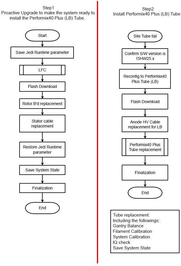
1 First Step of Proactive Upgrade
Procedure
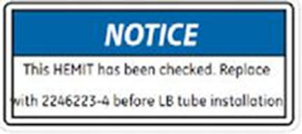
- notice
- Check the HEMIT Tank part number. If it’s 2237336, 2237336-2 or 2237336-3, Attach the “HEMIT
Notice Label - Replace before LB installation” on HEMIT Tank
(5445414). 2237336-4 or 2237336-5 are Optima CT660 HEMIT.
Order HEMIT FRU 2246223-4 and replace HEMIT Tank before LB Tube replacement at next step.
Figure 2. HEMIT Notice Label
- Execute “Save Runtime Parameters” from Generator Tool - JEDI.
- Execute LFC procedure. Refer to the following procedure. Refer to the (15HW25.x) Load From Cold.
- Perform Flash Download.
- Using CSD > Utilities > Flash Download.
- Press “Update”.
- Once the Gantry Hardware Flash Downloads successfully, select [Dismiss].
- Replace the Rotor Board.
- Remove Auxiliary Equipped. Refer to the Auxiliary Assembly Replacement.
- Place the Auxiliary Box on a flat surface, then remove the front cover.
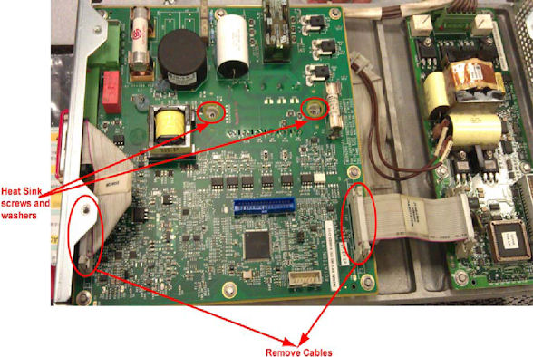
- Disconnect all cables to Rotor Control Board, unscrew all the
screws, and remove the old Rotor Control Board. Be sure to remove
screws and washers from heat sink also (see Figure 3).
Figure 3. Old Rotor Control Board Removal
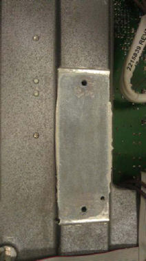
- Remove old thermal grease from groove.
Figure 4. Thermal Grease Removal
- notice
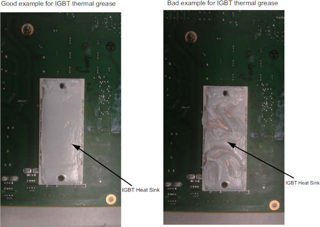
- Put on gloves and apply thermal conductivity grease (P/N 5134927)
on IGBT heat sink of the new rotor board (P/N 5456518) (see Figure 5), then install
the new rotor board to Auxiliary Box and re-connect cables.
Figure 5. Rotor control Board IGBT Heat Sink
- Torque the two screws to the following final value.
- Re-install the front cover of Auxiliary Box.
- Install modified Auxiliary Equipped. Refer to the Auxiliary Assembly Replacement.

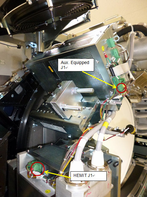
- Replace Stator cable (between Aux. Equipped J1 and HEMIT J1)
with provided one (2381533-2 rev3 JEDI 60 DC STATOR CABLE-ROHS).
Figure 6. Location of Aux. Equipped J1 and HEMIT J1
- Attach the labels.
- Turn off Axial Drive and HVDC switches on gantry service panel.
- Attach the provided labels.
Check and attach appropriate language caution labels.Before attaching label, thoroughly clean the machine surface where to attach the label. Refer to the table below for proper location and attaching method.
- Re-install Gantry covers.
-
Turn off 120VAC switch on Gantry Service Panel
-
Install Gantry front cover.
-
Install Gantry Left Side cover.
-
Install Gantry top covers.
-
Turn on HVDC, 120V
-
AC, and Axial Drive switches on the Gantry Service Panel. Press E-Reset.
-
Install Gantry Right Side cover.
-
- Execute “Restore Runtime Parameter” from Generator Tool - JEDI.
- Perform Save System State.
- Using CSD > Utilities > System State.
- Insert DVD or USB memory and press “Save System State”.
- Press “Dismiss” when it’s completed.
- Finalization
- Perform InSite checkout.
- Perform sanity scan with the following technique and confirm
they completed successfully.
Scout, Axial and Helical.
- Keep Perenna Anode HV Cable Assembly (5429083) at customer safe place for LB tube replacement.
- Discard old Stator cable.
- Send the following information to Performix.Plus@ge.com.
-
Ball Bearing Tube serial number
-
BB Tube Installation date
-
BB Tube kAs
-
BB Tube exams
-
System ID
-
|
2 Install Performix40 Plus Tube (This will be performed later date.)
Procedure
- Check the label on HEMIT Tank. If there is the label which
indicates to replace HEMIT Tank as below, order HEMIT FRU 2246223-4
and replace HEMIT Tank.
Figure 7. HEMIT Notice Label
- Confirm the system software version is 15HW25.x at CSD home page.
- Execute “reconfig” to change Tube type to Performix40
Plus (LB). Go to Hardware Tab and select Performix40 Plus (LB) from
Tube type.
Figure 8. Screen capture of reconfig for Tube type.
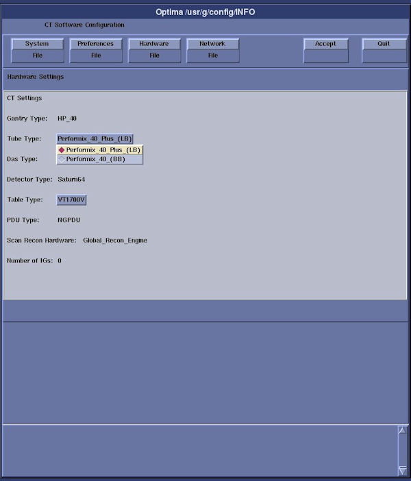
Refer to the System Configuration - RIO.
- Perform Flash Download.
- Using CSD > Utilities > Flash Download.
- Press “Update”
- Once the Gantry Hardware Flash Downloads successfully, select [Dismiss].
- Replace Anode HV Cable with provided one (5429083).
- Install Performix40 Plus Tube. Refer to the X-ray Tube Replacement.
- Checkout and update ProDiags schedule of InSite.
- note:Perform InSite checkout.
Skip this step if Insite (Class M) software is not applicable. ( Class M Restricted Service Software applies only to GEHC personnel)
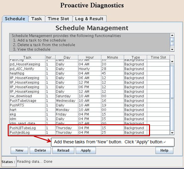
- Open command window, type "prodiags" and add new schedule of
ProDiags for the following tasks.
-
PushLBTubeLog
-
PushJediLog
Figure 9. Addition of new tasks.
-
- Update the task execution timing based on each site.
- Press “Apply” button and close the ProDiags window.
- Perform Save System State.
- Using CSD > Utilities > System State.
- Insert DVD or USB memory and press “Save System State”.
- Press “Dismiss” when it’s completed.
- Finalization
- Keep the original Anode HV cable (5128609-11) at customer safe place in further use.
- Send the following information to Performix.Plus@ge.com
-
Liquid Bearing Tube serial number
-
LB Tube Installation date
-
LB Tube kAs
-
LB Tube exams
-
System ID
-
3 Finalization
No finalization steps.