- Topic ID: id_18480375
- Version: 5.0
- Date: May 22, 2020 4:02:18 AM
HEMIT Air Removal Procedure
Prerequisites
Overview
This document provides the necessary steps to remove air from the JEDI 60 DC HEMIT tank. In the event that air is introduced into the HEMIT tank, shower artifacts caused by High Voltage spits can occur.
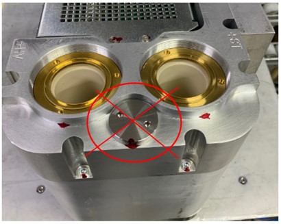
This procedure cannot be used for HEMIT2.0 tank. Fill plug on HEMIT2.0 should not be removed.
Figure 2. Do Not Remove Fill Plug
1 Preliminary Setup
Procedure
- Stop the rotor of X-ray tube in case of Liquid Bearing Tube before HVDC off. Refer to Liquid Bearing Tube Rotor stop procedure for details.
- Raise the Table to maximum height.
- Remove the side and top gantry covers. And slide the gantry front cover toward the table.
- Tilt the gantry backward to 20 degrees.
- Turn OFF Axial Drive and HVDC on the Service Switch Panel.
- Rotate the Gantry until the HEMIT Tank reaches the 9 o’clock position.
2 Apparatus Preparation
Procedure
- Rotate the Gantry slowly one revolution.
- notice
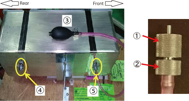
- Screw the nut of blind plug onto blind port (bladder valve) at the rear bottom of HEMIT Tank, and tighten the bolt of blind plug.
- Screw the nut of air pump onto bellow port (bladder valve) at
the front bottom of HEMIT Tank, and tighten the bolt of air pump.
Figure 3. Blind Plug and Air Pump Attachment
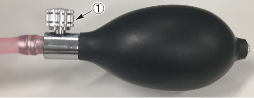
- To prevent squirting of oil from the tank or falling of the
liquid level, open the valve of air pump to relieve the internal pressure
of the tank, and tighten the valve again.
Figure 4. Valve of Air pump
- Attach the air vent cylinder as follows:
- Put a match mark for reinstallation as shown in illustration
below.
Figure 5. Mark
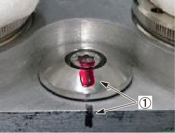
- Remove the oil filling plug using the 5 mm Hex key tool.
Figure 6. Oil filling plug and Hex screw
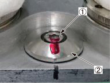 note:
note:In case of only a hex screw turns, remove the oil filling plug in one of the following methods.
-
Method A :
-
Remove the hex screw.
-
Apply loctite to the hex screw.
-
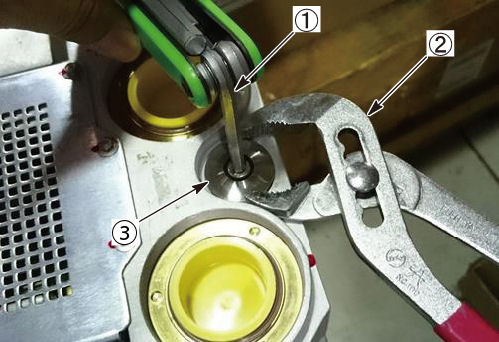
Fix the oil filling plug using pliers, and tighten the hex screw in a little more tight torque.
Figure 7. Pliers and Hex key
-
Take off the pliers holding the oil filling plug, and unscrew the hex screw with oil filling plug.
-
-
Method B :
-
Remove the hex screw.
-
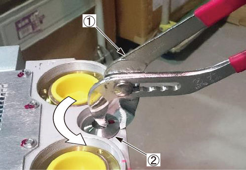
Pinch the oil filling plug with pliers as shown in illustration blow, and unscrew the oil filling plug.
Figure 8. Oil filling plug Removal
-
-
- notice
- Attach the air vent cylinder.
Figure 9. Air vent cylinder
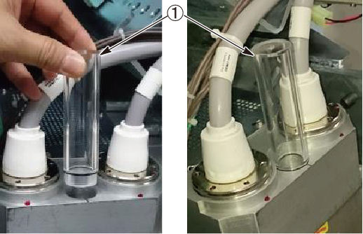

- Put a match mark for reinstallation as shown in illustration
below.
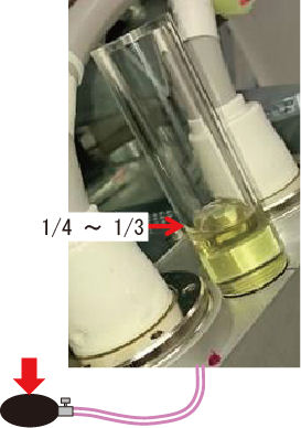
- Gently squeeze the air pump, and put oil in about 1/4 ~ 1/3
of the cylinder.
Figure 10. Oil level in the cylinder
3 Tank Air Removal
Oil level in cylinder will be lowered as air in tank is removed. Keep the oil level by using the air pump during the air removal precess.
Procedure
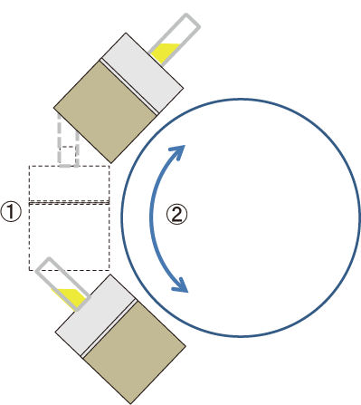
- Rotate the gantry (tank) slowly within the following angle range
until no air bubbles come out at any angle.
Figure 11. Air Removal
- Tilt the gantry to -10 degrees position.
- Remove the air from the tank in the same way as in Step 1.
- Tilt the gantry to zero degree position.
- Remove the air from the tank in the same way as in Step 1.
- Rotate the Gantry to position the HEMIT Tank at the 9 o’clock position.
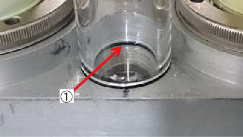
- Slowly open the valve of the air pump to align the oil level
to the O-ring position. Then remove the air vent cylinder.
Figure 12. Oil Level
- Operate the air pump again to adjust the oil level to the position of three screw threads from the upper edge of the oil filler port.
- Restore the oil filling plug and hex screw, and tighten the
screw in 4Nm torque. Or tighten the screw to the mark (see Figure 5).note:
Applying high strength type loctite (e.g. #263) to M6 hex screw may help easily remove the filling plug next time.
Do not apply the loctite to oil filling plug.
- Wipe off the leaked oil.
- Remove the blind plug and the air pump from the tank.
- Turn off the gantry 120VAC service switch.
- Restore the gantry covers and turn on all the three switches on the Service switch Panel.
4 Finalization
Procedure
- Perform System Scanning Test.