- Topic ID: id_17423473
- Version: 3.0
- Date: Jan 20, 2020 8:35:24 PM
Cradle Lock Assembly Replacement
Prerequisites
Overview
Procedure
- notice
- Raise the Table to its highest position.note:
If the Table up/down movement is inoperative, use the service power cable to raise the Table (refer to Enforced Table Elevation) .
- Move the cradle carriage to the mechanical OUT limit position by hand.
- Remove power from Table by turning off “120VAC”, “Axial Drive” and “HVDC” switches on the service switch panel.
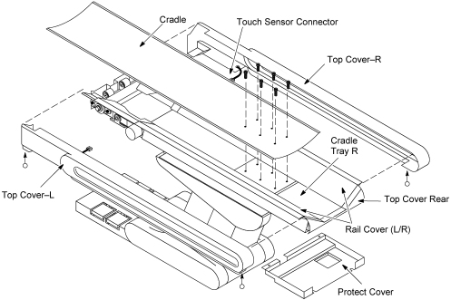
- Remove the following cover and component from the Table:
-
Cradle (Refer to Cradle)
-
Top Covers (L/R) (Refer to Table Covers Removal)
-
Rail Covers (L/R) (Four(4)x2 Screws)
-
Protect Cover (Four(4) Screws)
-
Cradle Tray–R (Six(6) Screws)
-
Top Cover Rear (Two(2) Screws)
Figure 1. Table Covers Removal
-
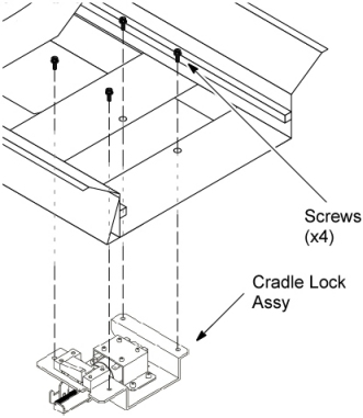
- Replace the Cradle Lock Assy with new one.
- Remove the Cradle Lock Assy by unscrewing its 4 screws.
- Install the new Cradle Lock Assy. Tighten the screws securely while pressing the Cradle Lock Assy to the front.
Figure 2. Cradle Lock Assembly Removal
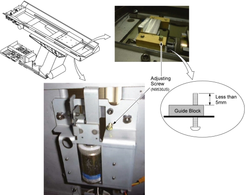
- Adjust the cradle lock block height using shim(s) (0.5mm, 1.0mm).
- Unscrew the existing screw, and install the block height adjusting
screw onto the cradle block.
Verify that the end point of the screw sticked out of guide block is less than 5mm.
Figure 3. Block Height Adjusting Screw
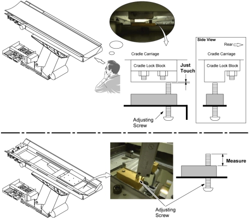
- Temporarily install the cradle onto the cradle carriage.
- notice
- Move the cradle backward until the cradle is locked by the cradle
lock assy.
and, turn the adjusting screw until the end point of the screw and the cradle lock block just touch.
- Remove the cradle and measure the adjusting screw (to one decimal
place).
Figure 4. Adjusting Screw Measurement
- Determine the proper thickness of shim(s) according to the formula:
Shim thickness = [Measured length] – 6.5
ex: If the measured length is 8.5mm, 2.5mm thickness shims (8.5–6.5=2) must be prepared.
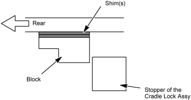
- Install the shim(s) between the block and cradle carriage (see Figure 5).
- Unscrew the adjusting screw, and tighten the screw removed in Step 6.a.
- Install the cradle, and verify that:
-
Move the cradle manually IN or OUT and the cradle is locked firmly by the cradle lock assy.
-
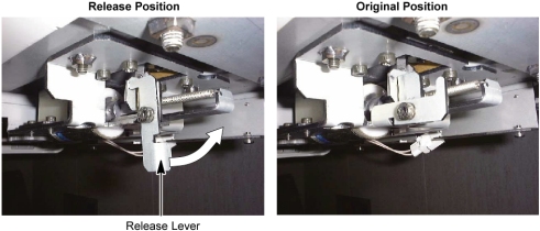
Release the cradle lock using the cradle lock release lever, then move the cradle manually IN or OUT so that the cradle could move smoothly with no lock.
If the cradle locking function does not work well, adjust the block position again.
Figure 5. Shim(s)
-

- Unscrew the existing screw, and install the block height adjusting
screw onto the cradle block.
- notice
- Return the cradle lock release lever properly to the original
position.
Figure 6. Cradle Lock Release Lever
- Restore the Table to original configuration.
|
|
Finalization
No finalization steps.