- Topic ID: id_15460886
- Version: 5.0
- Date: Jan 20, 2020 8:34:54 PM
(10HW02.x / 10HW33.x) Load From Cold - Optima CT660
Prerequisites
Overview
The following procedure describes and illustrates the system software loading process commonly referred to as the Load From Cold (LFC). It is important to follow the steps listed below in order.
1 Software Deliverable for RIO Console
Procedure
- CTT Operating System, Version 5.3.11
- CT Applications Software
2 Pre-LFC Checks and Information Gathering
Procedure
- Confirm that a current System State Backup Media is on site. If unsure of the status of the System State, execute System State Save Restore procedure found in the Software Chapter of this manual. Save a System State Backup to either DVD-RAM or USB Media.
- Remove all media from DVD Peripheral Towers before starting the OS Load of the LFC process.
- Record the following setting information:
- Connecct Pro (IP Address, Port Number, Etc.)PPS server information can be confirmed by the following procedure.
- {ctuser@hostname} cd /usr/g/ctuser/resources/pps
- {ctuser@hostname}
head -12 ppsserver.cfg
Output Example:
PPS_REMOTE_AE_LIST =
{
# AppTitle,IPAddress,IPPortNo,HostName;
DICOM_TEST_RMT,3.70.204.86,4500,Default;
- Record the PPS Information per the following EXAMPLE:
- Exam Split (perform the following to determine VES or HES)
- {ctuser@hostname}su -
- Password:<password>
- {root@hostname}
ls -l ~ctuser/ves/.hesModenote: There are no spaces in the phrase~ctuser/ves/.hesMode.
- Examine the results. If the results are similar to:
-rw-r--r-- 1 ctuser users 0 Apr 3 12:43 /usr/g/ctuser/ves/.hesMode
then HES (Hard Exam Split) mode is configured.
- EKG Monitor (model)
- Injector (pressure Unit) on CSD menu
- Connecct Pro (IP Address, Port Number, Etc.)
3 Operating Software (OS) Load
Procedure
- Unplug the Hospital Network (HSP) cable from rear Console bulkhead.
- Remove the Operator Console front cover per the prescribed procedure Console Cover Removal and Installation.
- Insert the OS Disk into the Host Computer DVD Drive. See the following illustrations.
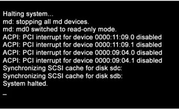
- Shutdown and Power Cycle Operator Console (wait approximately
10 seconds for cycle power)
Figure 1. Monitor Display – System Halted
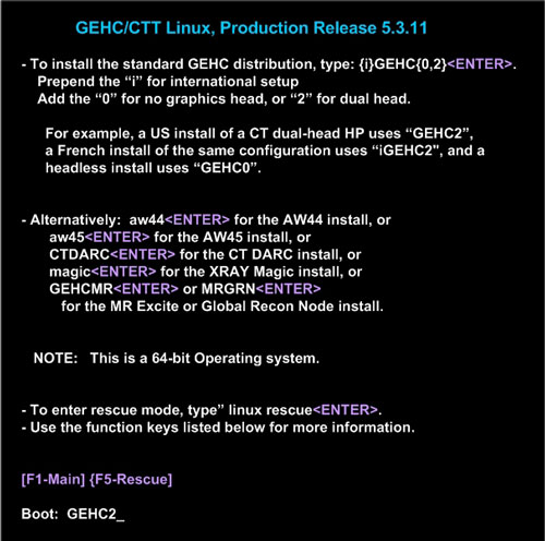
- As the Host Computer restarts, the boot process messages appear. After the booting process completes the boot: prompt appears.
- At the “boot:” prompt, type the following:
Type: boot: GEHC2
Figure 2. Monitor Display – Boot Prompt
- After the OS is loaded on the Host Computer, the Complete Window
appears.
Figure 3. Monitor Display – OS Load Complete
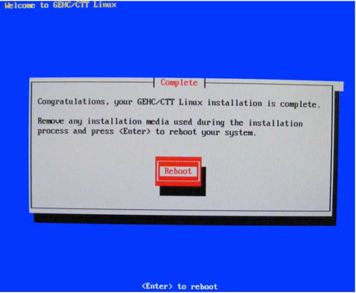
- Remove the OS Disk from the Host Computer DVD drive when it ejects and close the tray. Press Enter to Reboot.
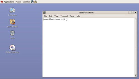
- The Host Computer begins to reboot.note:
Do not insert the Applications Software DVD into the Host Computer until the Host Computer has completed rebooting and a Terminal Window appears, displaying the prompt: [root@localhost ~]#.
Figure 4. Terminal Window – After OS Load and Reboot
 note:
note:Dual Monitor Displays: From this point in the procedure, the dual monitor display will appear reversed (Right monitor video will display on Left monitor and Left monitor video will display on Right monitor). This is normal, do not move monitor video cables! This also impacts the behavior of the mouse cursor. The mouse cursor will not cross over the middle junction of the dual monitor display. Instead the mouse cursor will need to be dragged to the outside of the dual monitor display in order to change from one monitor to the next. To place the mouse on the right monitor, drag the mouse outside the left monitor’s LEFT side. The mouse will then appear on the right monitor. This condition will be resolved after the Application Software is loaded on the system.
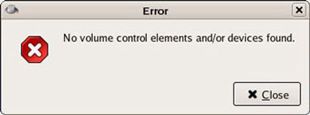
Error Window After OS Bootup: After the OS Bootup, an Error Window will appear. This is normal and is related to the new Host Computer's (HP Z400) on board audio controller. When Error Window appears, close the error window by clicking on the Close button. This error is the result of driver configuration for the on-board audio hardware and will be resolved once the Application Software load is completed on the system.
Figure 5. Error Window - After OS Load and Reboot
 note:
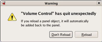
note:Warning Window During APPS Load: After the OS Bootup and during the APPS load, a Warning Window will appear. This is normal and is related to the Host Computer. When Warning Window appears, ignore it (take no action). This warning message is the result of driver configuration for the on-board audio hardware and will be resolved once the Application Software load is completed on the system.
Figure 6. Warning Window - During APPS Load
4 Applications Software (APPS) Load
Procedure
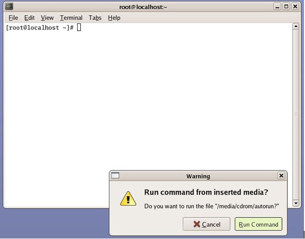
- Open the tray on the Host Computer DVD Drive.
- Insert the Applications Disk into the DVD Drive and close the
tray.note:
The Apps Software Disk will open and run automatically.
- Select Run Command in the Warning box.
Figure 7. Apps Run Command Window
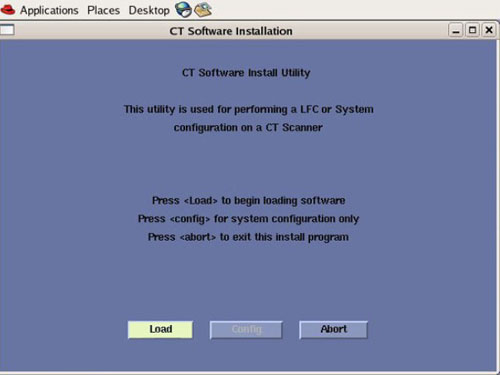
- Select Load in the CT Software Installation
window.
Figure 8. Apps Load Command Window
- System State decision for Install INFO decision box will appear. Select Yes.
Figure 9. Install INFO Window
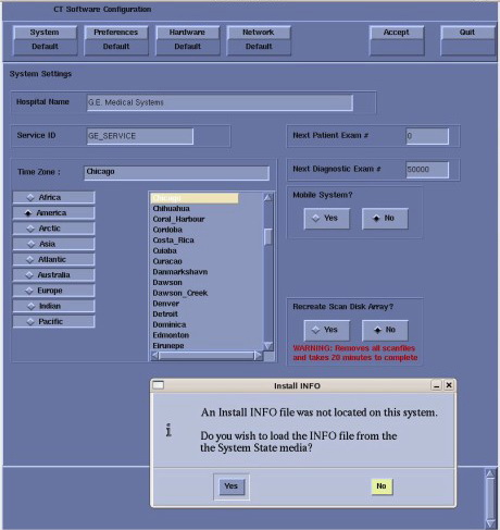 note:
note:If a valid and current System State Backup media is not available, answer No and manually configure the Hardware Tab to define System and Console Type in accordance with the procedure Manually Configuring System INFO.
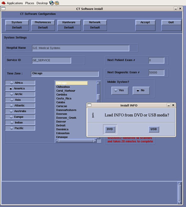
- System State (Install INFO) Media Type decision window will
appear
Select DVD or USB based on media type available.
Figure 10. System State Media Type Window
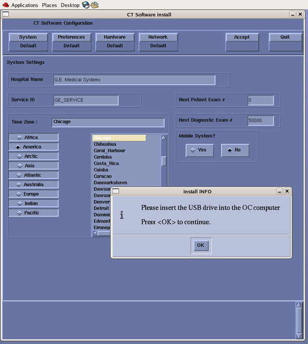
- Insert the System State Backup Media (DVD-RAM or USB). note:
DVD-RAM Media: Insert DVD-RAM Media into the DVD-RAM Drive located in the DVD Peripheral Drive Tower.
USB Media: USB Media can be inserted in any of the USB ports located on the console. Recommend using the Service USB port located next to the console's power switch.
Select OK.
Figure 11. Install INFO - System State DVD Install Window
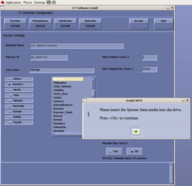
Figure 12. Install INFO - System State USB Install Window
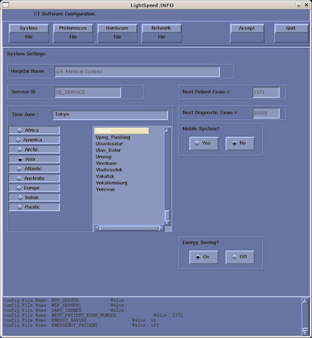
- The Install INFO on the System State Backup Media will be read
and if a valid System State Backup has been inserted, an LightSpeed/INFO
window will become active.
Select Accept.
Figure 13. Install INFO - Accept Window
- The Install INFO on the System State Backup Media will be displayed
and a confirmation window will appear.
Select Yes.
Figure 14. Install INFO - Confirm Window
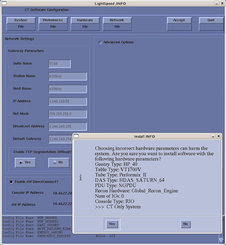 note:
note:Install INFO detail in illustration will differ depending on System type. Verify that the Install INFO detail is correct for the system before selecting [YES].
- System Install INFO will be now used to create the CT Application load routine. Do not remove the Apps Disk until completed.
- When completed, the Operator Console will automatically reboot.
- After the Host Computer reboots, a pop-up window will appear
Figure 15. CT Software Auto-Start Disabled Pop-Up Windows
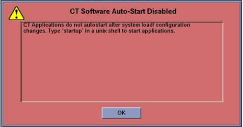
Click OK to close window.
note:Remove APPS disk from Host Computer.
Remove System State Backup Media for either DVD-RAM drive or USB port.
5 LFC Menu - RIO Console Software Load
Procedure
- To launch LFC Menu, open a Terminal Window, and log on as root:
- Type: {ctuser@hostname} su –ENTER
- Type the root password and press ENTER
- Type: [root@hostname] /usr/g/scripts/LFC/startLfcMenu.shENTER
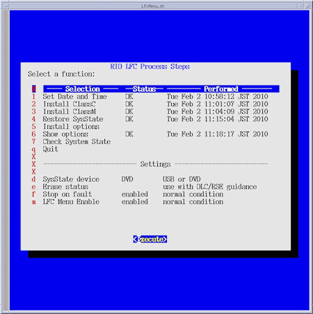
- A window will be displayed showing the LFC Menu. note:
The LFC Menu Utility provides the tools necessary to complete a LFC process without the use of the Linux Command Line. For more detailed information on the operation of this menu click here: LFC Menu Tutorial
Keyboard Control C Functionality:
Using CTRL + C keys to abort LFC process or to close any shell and/or pop-up windows will cause the LFC Menu to display a fault condition for the selected process step.
Windows must be closed with either: a) Right click the window title bar, then selecting Destroy from the menu. b) Left click the icon on the upper left corner of the window, then selecting Close from the menu.
LFC Menu Settings:
By default the System State (SysState) Device setting is configured for DVD. If using USB Media, change SysState Device Setting to “USB” by selecting LFC Menu “d”
Figure 16. LFC Menu Window
- Select Set Date and Time (Menu Selection # 1)
Select Execute, the Set Date and Time Utility will open in a shell window.
Follow on screen instructions for setting the correct date and time.
Upon completion of the Set Date and Time Utility, close the shell window to return to the LFC Menu.
- Select Install ClassC (Menu Selection # 2)
Selecting this item performs install of Advanced Service Software. (Not required for System operation.) Skip step if not applicable.
note:Class C Advanced Service software applies only to GE Healthcare personnel and customers with an Advance Service Limited License agreement.
- Select Install ClassM (Menu Selection # 3)
Selecting this item performs install of Advanced Service Software. (Not required for System operation.) Skip step if not applicable.
note:Class M Restricted Service software applies only to GE Healthcare personnel.
- Select Restore System State (Menu Selection # 4)note:
When this menu selection is chosen, the System State Save and Restore Utility will be launched. See System State Save and Restore procedure in the Software Installation section of the Software Chapter in the Service Documentation for more details.
If previously installed, all Options will be restored during the Restore System State.
Remember to set LFC Menu Settings (Selection “d”) to USB if using USB Media. LFC Menu is defaulted to DVD-RAM.
Insert the System State Media in either the DVD-RAM Drive of USB Port depending on media chosen earlier in this procedure, then select Execute.
A shell window will open and the System Stated will be restored. Several pop-ups will appear requesting configurations settings based on Options being restored. Select appropriate settings for the Options.
Upon completion of the Restore System State, a pop-up will appear reminding that a reboot will be required. Click OK, but do not reboot at this time. Close the shell window to return to the LFC Menu.
- Optional Menu Selectionsnote:
Install Options (Menu Selection # 5)
If this menu selection is chosen, the Install Software Options Utility will be launched. See Install Software Options procedure in the Software Installation section of the Software Chapter in the Service Documentation for more details. This menu selection is only required when a valid System State is not available. (Valid means: Current and Created after Options were loaded on system) If a valid System State was restored in the previous step “Restore System State”, this step may be skipped.
After selecting Execute, a shell window will open and the Install Software Option Utility will be launched. Upon completion of the Install Software Options Utility, a pop-up will appear reminding the user that a reboot will be required. Click OK. Close the shell window to return to the LFC Menu.
note:Show Options (Menu Selection # 6)
If this menu selection is chosen, the system will display all installed Options. This menu selection should be used to verify that all applicable Options are installed.
After selecting Execute, a shell window will open and the current installed Options will be displayed. Upon completion of the Show Options, close the shell window to return to the LFC Menu.
* Example only. Customer specific. Options displayed will be differ system to system.
note:Check System State (Menu Selection # 7)
If this menu selection is chosen, the system will display the differences between the INFO file on the System State media to the INFO file on the system. Any differences are identified in RED. This selection requires the System State media to be inserted in the applicable device (USB Port or DVD-RAM Drive) prior to executing selection.
After selecting Execute, a shell window will open and the System State Comparison List will be displayed. Upon completion of the Check System State, close the shell window to return to the LFC Menu.
“RECREATE - ARRAY” may have difference and assigned as RED, but ignore it.
- Select Quit (Menu Selection # 8)
Then select Execute, the LFC Menu will check that the minimum procedural steps required for a LFC have been completed.
A pop-up window will appear confirming LFC Status.
Click Yes if satisfied that all necessary LFC Menu selections have been completed.
note:Selecting this menu item will terminate the LFC Menu. Only select this menu selection once all steps have been completed.
Once the LFC Menu is turned off (either by confirming the “Quit” Process selection or by disabling the LFC Menu in the LFC Menu Settings), it will remain disabled. To turn the LFC Menu back on will require the following command string to be entered in a Linux Terminal windows:
Open a Terminal Window, and log on a root.
Type:
[root@hostname] /usr/g/scripts/LFC/startLfcMenu.sh ENTER
- Reboot the System
In the Terminal Windows used to launch the LFC Menu, type:
[root@hostname] reboot ENTER.
6 Tube Install Certification
Procedure
- Perform the Tube Install Certification procedure.
- When completed, continue with Flash Download.
7 Flash Download
Procedure
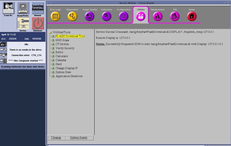
- Perform the Flash Download Utility found on the Common Service
Desktop – Utilities Tab, select Flash Download.
Figure 17. Common Service Desktop – Utilities Tab, Flash Download
 note:
note:The Flash Download takes 5 - 30 minutes, depending on which subsystems need firmware updating.
- When the Flash Download Window opens,
Select Update.
Figure 18. Flash Download Window
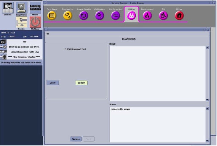
- Once the Gantry Hardware Flash Downloads successfully, select Dismiss.
- Close the Common Service Desktop.
- Reconnect the Hospital Network cable at the rear of the Operator Console that was disconnected at the beginning of the LFC.
- Select Shutdown icon on the Desktop and restart the system.
8 Final Save System State
Procedure
- Perform the System State Save and Restore procedure and save a System State Backup to either DVD-RAM or USB Media.
- Save the System State Backup media in a safe and secure location for future service activity.
9 Finalization
Procedure
- If applicable, install any Service Pack updates related to this
release. note:
Follow Service Pack load instructions supplied with the Service Pack Software.
- Refer to System Scanning Tests in the Functional Checks chapter of this manual to confirm proper operation.
- Reinstall Console Front Cover.