- Topic ID: id_16157679
- Version: 2.0
- Date: Nov 7, 2019 8:54:06 PM
System Configuration - Cyber Security Enhancement
Prerequisites
Overview
The following procedure describes and illustrates the system configuration process for RT System with Cyber Security Enhancement. It is important to follow the steps listed below in order.
1 Reconfig
Procedure
- Shut down Applications from the Common Service Desktop, Utilities Tab.
- Open a Terminal Window, and log on as root:
- Type: {ctuser@hostname} su –ENTER
- Type the root password and press ENTER
- Launch the Configuration utility:
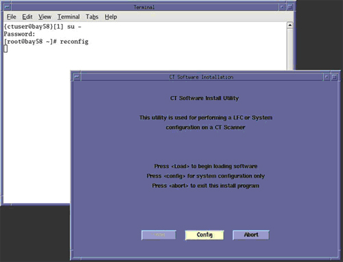
Type: [root@hostname] reconfig ENTER
- The CT Software Install Utility Window will appear.
Figure 1. CT Software Install Utility Window
 note:
note:The following shows the screens that are used to change the configuration of the system. These screens are the same as those used for the Software Configuration during Load From Cold. The actual screens will vary depending on the current configuration of your system.
- Click CONFIG to display the System Settings window.note:
The following configuration pages show the screens that are used to change the configuration of the system.
These screens are the same as those used for the Software Configuration during Load From Cold.
The actual screens will vary depending on the current configuration of your system.
Figure 2. System Settings Window
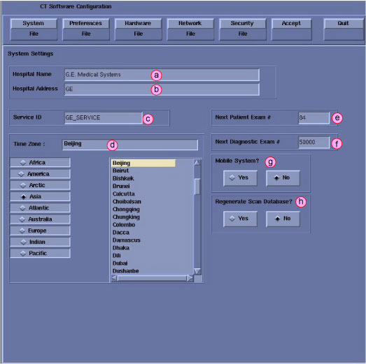
- Configure System Settings.
- Hospital Name (Illustration 2, item a) - Configures the name that will show up on images produced by this scanner. Example: ST MARY'S HOSPITAL
- Hospital Address (Illustration 2, item b) - Configures the hospital address.
- Service ID (Illustration 2, item c) - Issued by the Service organization. Example: 262785CT2 (no spaces, 14 character limitation)
- Select the Time Zone for the site.
- Next Patient Exam Number - Customer selected. At initial system installation, Type: 1.
- Next Diagnostic Exam # - Configures the next Exam number the scan user interface will use. Customer Selected. At initial system installation, Type: 1.
- Mobile System - Select to tell the software if this CT is in a mobile environment or not.
- Regenerate Scan Database.
- Click PREFERENCES to display the Preferences Settings window. (See Figure 3.)
Figure 3. Preferences Settings Window
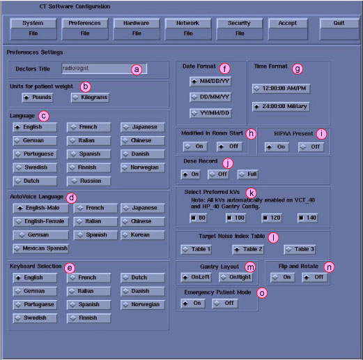
- Configure Preferences Settings.
- Doctors Title - Enter the title for the Doctor (e.g., radiologist.)
- Units for Patient Weight - Tells the software whether pounds or kilograms are being used.
- Language - Configures the language to be displayed on the Application screens.
- AutoVoice Language - Configures the language heard in the scan room.
- Keyboard Selection – Configures the language specific keyboard character set.
- Date Format - Configures the format in which the date will be displayed on the images.
- Time Format - Configures the format in which the time will be displayed on the images.
- Modified In Room Start - Be sure "Off" is selected, unless the site is in Japan, in which case, this feature should be "On".
- HIPAA Present - Be sure “Off” is selected unless told differently.
- Dose Record – Configures support for DICOM Dose SR Record option
for saving dose information with study. Default is “ON”.
The dose information is saved in a DICOM structured report. The
DICOM standard defines a new DICOM X-Ray Radiation SR SOP class, which
the other systems must support. The Dose SR feature saves an exam's
dose information in this format.
-
Select ON - Saves the dose information in a DICOM Enhanced SR SOP Class
-
Select OFF - Turns off option
-
Select FULL - Saves the dose information in a DICOM X-Ray Radiation Dose SR SOP Class
note:This preference shall not be enabled unless specifically requested by the Customer and the Evaluation of Dose SR Compatibility procedure has been executed and indicates that the other hospital systems support the Dose Report SOP classes.
-
- Preferred Fast Cal KV - Configures the preferred kV that the Fast Cal Routine will calibrate (80, 100, 120, 140 in the Selected Preferred Fast Cal KV field). The default selections are 80, 100, 120, and 140. All defaulted ON for VCT systems. All defaulted On for CT750 HD systems.
- Target Noise Index Table - Be sure Table 2 is selected.
- Gantry Layout - Configures the preference for Patient loading. Choose correct orientation depending on site specific Gantry layout.
- Flip and Rotate - Configures the preference for allowing the
Flip and Rotate feature to be turn on in the User Interface on the
(Left) SCAN Monitor. This preference allows the Customer to apply
custom orientation changes based on Exam Type and Reconstruction methods
on DICOM images that will be transferred to PACS and related systems.note:
This preference shall not be enabled unless specifically requested by the Customer and the Evaluation of Image Flip and Rotate Compatibility procedure has been executed and all DICOM test images pass orientation check
- Emergency Patient Mode - Configures the preference for allowing the emergency patient to be turned on in the user interface.
- Click HARDWARE to display the Hardware Settings window.
Figure 4. Hardware Settings Window
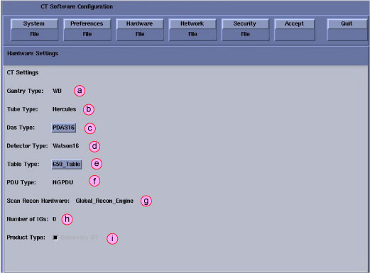
- Configure Hardware Settings.
- Gantry Type - Indicates the type of Gantry that is installed.
- Tube Type - Indicates the type of X-Ray Tube that is installed.
- DAS Type - Select the DAS type: PDAS16.
- Detector Type - Indicates the type of Detector that is installed (Watson16).
- Table Type - Select the Table type according to site configuration: VT1700 and 650_Table are optional.
- PDU Type - Indicates the type of PDU that is installed.
- Scan Recon Hardware - Indicates console type.
- Number of IGs - Indicates the number of IGs installed.
- Product Type - Indicates the System type
- Click NETWORK to display the Network
Settings Screen.
Figure 5. Network Settings Window
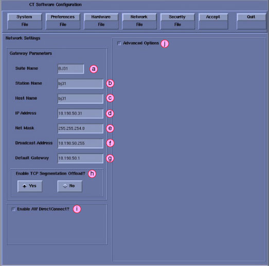 note:
note:This screen provides the ability to declare the CT system on a hospital network. Key information such as Host Name, IP Address, Net Mask (for CT systems on a subnet) must be obtained from the hospital network administrator.
- Configure Network Settings.
- Enter the Suite Name. The Suite name must start with a letter, followed by three (3) alpha-numeric characters. Total must be four characters long. The name of the OC interface will be <Suite Name>_OC, within the scanner subnet. Typically, you should use su01 or ct01 (“su” and “ct” must be lowercase), unless the customer prefers a different suite name.
- Enter the hospital provided Station Name.
-
MUST NOT exceed 16 characters.
-
MUST only contain the following characters: a through z, A through Z and 0 through 9.
The Station Name is typically stmary or ct01.
note:If left blank, the Station Name defaults to the Host Name.
-
- Enter the hospital provided Host Name. The Host Name identifies
the network hostname and AE Title of the CT system to the hospital’s
network. The Host Name:
-
MUST NOT exceed 16 characters
-
MUST only contain the following characters: a through z, A through Z and 0 through 9.
-
MUST have at least one of the following characters: a through z or A through Z. (Host Name MUST be Alpha or Alpha-Numeric)
The Host Name is typically stmary or ct01.
-
- Enter the hospital provided IP Address for the system
- Enter the hospital provided Net Mask Address for the system.
- Enter the hospital provided Broadcast Address for the system.
- Enter the hospital provided Default Gateway Address for the system.
- Enable TCP Segmentation Offload - Default YES. If network transfers to certain PACS systems are slow, this can be set to No and may increase the transfer speed.
- Enable AW DirectConnect if option provided with system. Reviewing the order information to see if option is included.
- Items j is visible only when Advanced Options is selected.
-
Enter the hospital provided NIS Domain Name and IP Address for the system, if NIS is utilized on site.
-
Enable Network Time Protocol, if so instructed by hospital. Hospital must have an NTP Server available and the scanner should be synchronized with the Hospital’s time.
-
Enable Change DARC Subnet, if so instructed by hospital.
note:Only enable this feature if there is an IP conflict between the system local network and the hospital local network. The console utilizes a DHCP Server to configure the Console local network address for communications between Host, Gantry/Table and Reconstruction Engine Computers. Default local addresses in the console use the following local Octets: 172.16.xxx.xxx. And this function changes the address to 169.254.0.xxx.
-
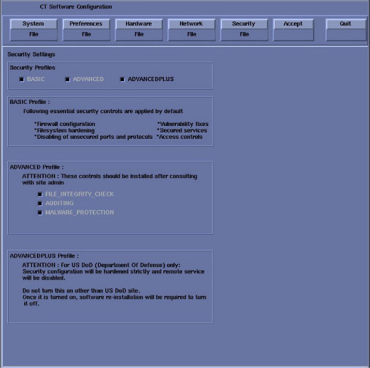
- Click SECURITY to display the Security Configuration window.
On Security Tab, select ADVANCEDPLUS on Security Profiles if it is not.
Figure 6. Security Configuration Window
- Review all screens to be sure the information entered is correct before proceeding to the next step.
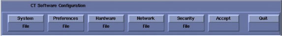
- Click ACCEPT to accept the changes made.
Figure 7. Accept Configuration Window
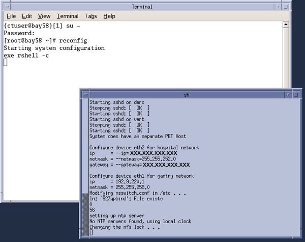
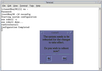
After clicking ACCEPT the system configures the system. While the configuration is going on, the results are displayed in a Shell window that closes when the loading process is complete. (See Figure 8.)
Figure 8. Shell Configuration Window
- When the configuration changes are complete, the system displays a prompt to reboot.
- Click YES. (See Figure 9.)
Figure 9. Configuration Complete Window
- The system will automatically log in as ctuser after the reboot. Select [OK] on the Autostart Disabled popup message.
- If not already done so, right mouse click anywhere on the blank desktop to display the ToolChest and select UnixShellLeft or UnixShellRight.
- Open a Terminal Window, log on as root:
- Type: {ctuser@hostname} su —ENTER.
- Type the default root password noituloveR#321 and press [Enter].
- At this time the customer’s Sys Admin will need to create
and enter a new root password. The system automatically requests a
new root password after entering the default root password.note:
New OS root password requires:
-
14 characters minimum
-
Have at least one uppercase alphabetic character
-
Have at least one lowercase alphabetic character
-
Have at least one numeric character
-
Have at least one non-alphanumeric special character
-
Passwords must not contain more than three consecutive repeating characters
-
Passwords must not contain personal information such as names, telephone numbers, account names, birthdates, or dictionary words
-
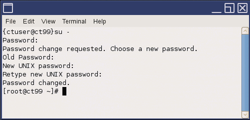
- In Shell window, enter old (default) password, followed by new
password, then confirming new password by reentering it a second time.
Figure 10. Root Password Reset
2 EA3 Account Settings & CT Applications Startup
Procedure
- Open a shell and login as root. Type: [root@hostname] reboot <Enter>.
- Allow the System to come up fully into Application Mode. If the CT Applications fail to start automatically, open a Shell Window and type: {ctuser@hostname} st <Enter>.
- After a while, logon screen will appear. Login as EA3 Admin
user.note:
If the logon screen does not appear, enable the “HIPAA” by Configure HIPAA in Common Service Desktop.
Figure 11. Logon Screen

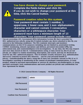
- Login as default Administrative Privileges User :
User ID : admin
Password : install
- Reset "admin” User password.
At this time the customer’s Sys Admin will need to create and enter a new password. “admin” password is owned by the customer’s Sys Admin.
Figure 12. “admin” User Login - Password Update
 note:
note:New “admin” password requires:
-
15 characters minimum
-
Have at least one uppercase alphabetic character
-
Have at least one lowercase alphabetic character
-
Have at least one numeric character
-
Have at least one non-alphanumeric special character
-
Passwords must not contain more than three consecutive repeating characters
-
Passwords must not contain personal information such as names, telephone numbers, account names, birthdates, or dictionary words
Figure 13. “admin” User Login - Password Update Complete
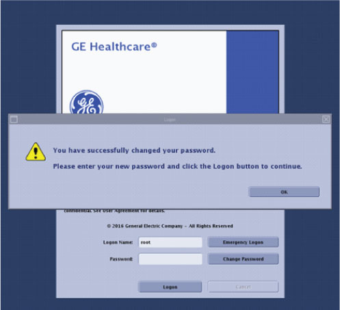
-
- Login to “admin” User using new password. System will launch CT Applications.
- CT Applications Desktop will now appear.
- Have Sys Admin create the “service” User account
with “GE Service” and “administration” or
all Group privileges, using EA3 Browser. See EA3 Instruction in the
User Manual for modifying User accounts.
The “service” User Name should be set to the Sys Admin’s preference, either actual FE name or a generic name such as service.
Multiple service accounts may be created if so desired by Sys Admin.
Service (FE) will need to enter for the first time a 15 character password.
note:FE must know service password, but Sys Admin owns password, only the Sys Admin can edit or create accounts in EA3.
note:New “service” password requires:
-
15 characters minimum
-
Have at least one uppercase alphabetic character
-
Have at least one lowercase alphabetic character
-
Have at least one numeric character
-
Have at least one non-alphanumeric special character
-
Passwords must not contain more than three consecutive repeating characters
-
Passwords must not contain personal information such as names, telephone numbers, account names, birth dates, or dictionary words.
-
- Restart CT Applications and login to “service” User account and proceed to Tube Install CertificationTube Install Certification after logging in as EA3 user successfully.
3 Tube Install Certification
Procedure
- Run Tube Install Certification Utility found on Common Service Desktop - Configuration Tab.
- Restart system.
4 Flash Download
Procedure
- Perform Flash Download Utility found on the Common Service Desktop - Utilities Tab, select Flash Download.
- When the Flash Download Window opens, select Query.
- Check if System is reporting that any of the subsystems require flashing. If subsystem displays “INVALID Version”, click [Update] to load latest firmware.
- Close the Common Service Desktop.
- Select Shutdown icon on the Desktop and restart the system.
5 Host BIOS Settings Update
Procedure
- If CT Applications are running, power cycle the system by clicking the Shutdown icon on the desktop.
- After the System has completed the shutdown process, turn Off Operator Console power. Wait 30 seconds, then turn power On.
- On system restart, Press <F10>. Use arrow keys to set BIOS
password. From BIOS menu, navigate to Security > Setup BIOS Administrator Password. Set
the password for field "Enter BIOS Administrator Password” and
enter same password for "Please re-enter your password to confirm".note:
New password requires 10 characters minimum.
- Configure to only boot from the system boot device.
From BIOS menu, navigate to Advanced > Boot Options -> Optical Media Boot Support -> Check the device selection status for “Optical Media Boot Support”. If it is "Enable" then change to "Disable".
- Now to save the configuration changes, choose Main -> Save Changes and Exit. To confirm applied changes, select "Yes" from confirmation message "Are you sure you want to save changes and Exit ?".
- Restart and then press <F10> to confirm BIOS settings.
6 Finalization
Procedure
- Perform the System State Save Restore procedure and save a System State Backup to either DVD-RAM or USB Media.
- Save the System State Backup media in a safe and secure location for future service activity.