- Topic ID: id_15460244
- Version: 2.0
- Date: Nov 8, 2018 1:36:40 AM
LightSpeed VCT FREEdom Console Upgrade
Prerequisites
Overview
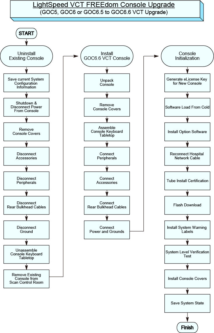
This document describes and illustrates the steps necessary to upgrade a LightSpeed VCT GOC5, GOC6 and GOC6.5 Operator Console with a GOC6.6 VCT Operator Console.
Refer to the flowchart in Figure 1 for the overall upgrade process. .
Figure 1. GOC5, GOC6 and GOC6.5 to LightSpeed VCT FREEdom Console Upgrade (GOC6.6 VCT) Flowchart
Please review Section 3.5, Required Conditions, before proceeding with this upgrade procedure.
1 Inventory Upgrade Kits
Before starting upgrade and console disassembly, check contents of Upgrade Kit to make certain all supplied parts are present and have not been damaged in shipping. (Refer to Table below)
2 Save Current System Configuration Information
2.1 Identify Detector/DAS type
There are three types of VCT Detectors/DAS released, VDAS (Sherlock Detector), HDAS (HALO Detector), and HDAS_Saturn_64 (Saturn Detector). They are identified on the Common Service Desktop Home page "Data Acquisition System" type listed as VDAS, HDAS, or HDAS_SATURN.
Procedure
- Before un-installing existing Console, identify which Detector/DAS type is present with system being upgraded.
- Look at the Common Service Desktop home page for the DAS type entry. If the DAS type = VDAS64 or HDAS64, then you have a Sherlock or HALO detector and system software will need to be reloaded after installing the new Console. The GOC6.6 VCT console comes loaded for the DAS type = HDAS_SATURN_64, which is the Saturn detector.
- Record the DAS type in the System Information Sheet.
2.2 Record the Installed Software Options and Other System Information
Procedure
- Record the installed software options and other system information such as ConnectPro and Exam Split in the System Information Sheet.
- -
2.3 Save System State on Existing Console
Procedure
- Save a new System State in accordance with Software - GOC6.6 VCT > Software Installation > System State Save & Restore in the LightSpeed VCT Service manual supplied with this upgrade.
- -
3 Uninstall Existing Operator Console
3.1 Image and Scan Database Resets on Host Computer
To maintain data and patient privacy, it is necessary to erase all Personal Healthcare Information (PHI) from the system before it is uninstalled. Perform the following as the last step before shutting down the existing console.
Procedure
- Reset (Erase) the Image Database on the system. Follow Host Computer Image Database Reset procedure found in the Software Chapter of the LightSpeed 7.X Service manual.
- Reset (Erase) the Scan Database on the system. Follow instructions found in the Align/Setup/Cal Chapter of the LightSpeed 7.X Service manual. Align/Setup/Cal > Console (GOCx) > System Configuration procedure.
On the System Tab of the System Configuration Utility, perform the following:
-
Remove the customer name, replace with GEMS
-
Remove the Service ID, replace with GEMS
-
Under Regenerate Database, select YES
On the Network Tab of the System Configuration Utility, perform the following:
-
Remove the site specific network information (ex: Names), replace with GEMS
-
Remove the site specific network information (ex: IP Addresses) in Network Settings and Advance Options.
Select ACCEPT button.
note:The Reset (Erase) of the Image and Scan Databases will remove PHI information from the system but may not meet local regulations for data removal/deletion. If local regulations require specific data removal/deletion criteria, follow local procedures for PHI removal from system.
After completion of System Configuration (reconfig), reboot the system:
-
Select OK on the Autostart disabled popup message
-
Open a terminal window and type : st
-
When the system is booted into Applications mode, select IMAGE WORKS
-
Confirm that patient image data is not present.
-
3.2 Shutdown and Disconnect Power on Existing Operator Console
Procedure
- Select one of the following methods to power off the Operator Console:
- If Applications are running, click on Shut Down and select Shutdown.
- If Applications are down, open a Unix Shell using the Toolchest. Type:
{ctuser@hostname} haltENTER
The Operator Console Monitor will display a System Halted message when it is acceptable to power off the Operator Console.
- Power OFF the Operator Console at the front panel switch.
- Remove the Console’s incoming Twist-N-Lock Power Cable from rear of the Console.
- Perform Lockout / Tagout as described in Safety – Equipment Service – Lockout / Tagout / PPE in the LightSpeed VCT Service Manual.
3.3 Remove the Console Covers
Procedure
- Move the console away from the wall to allow clear access around the console.
- Remove the console front and rear covers and set aside.
3.4 Disconnect Accessories/Options on Existing Operator Console
Disconnect the Accessories in the following table from the existing Console. Follow table instructions for disposition of items removed.
Procedure
- Remove the Monitors from the existing Console by disconnecting the Video Cables from the Host Computer, and Power Cables from the Console Outlet Box inside the Console. These cables will be returned with the Console.
- Disconnect and remove the Trackball from the Console.
- Disconnect and remove the Barcode Reader (if so equipped) from the Console.
- Disconnect and remove the Remote Monitor Video Amp/Splitter (if so equipped) from the Console. Make sure that all cable connections are labeled. Disconnect the Video Amp/Splitter power cable from the Console Outlet Box inside the Console. Keep these cables that were connected to the Video Amp/Splitter, as they will be needed for new GOC6.6 VCT Console.
- Disconnect and remove the Digital DASM (if so equipped) from the Console. Disconnect the SCSI I/F cable from the Host Computer. Disconnect the Digital DASM power cable from the Console Outlet Box inside the Console.
- Disconnect and remove the Service Modem (if so equipped) from the Console. Disconnect the RS232 cable from the Host Computer. Disconnect the Service Modem power cable from the Console Outlet Box inside the Console.
3.5 Disconnect Peripherals on Existing Operator Console
Disconnect the following peripherals in the following table from the Console. Follow table instructions for disposition of items removed.
Procedure
- Disconnect and remove SCSI Peripheral Tower from console.
- Disconnect the SCSI Cable from the Host Computer and Power Cable from Console Outlet Box inside the console.
These cables will be returned with Console.
- Disconnect and remove the SCIM Assembly from console.
- Disconnect the SCIM Cable from the under side of the SCIM Assembly.
- Disconnect and remove the Mouse from the console.
- Disconnect the Keyboard PS2 cable from the Upper Bulkhead Panel.
- Disconnect and remove the Keyboard from the console.
- Disconnect the Keyboard PS2 cable from the Upper Bulkhead Panel.
3.6 Disconnect Rear Bulkhead Cables on the existing Operator Console
Procedure
- Disconnect all cables connected to the Rear Bulkhead Panel on the existing Console. These include the Network, Fiber Optic Link, and Gantry DB25 Cables.
- Make sure that all cables are clearly labeled as to their function and source.
3.7 Disconnect Ground Cables on the existing Operator Console
Procedure
- Remove the Scan Room Patient Reference Ground cable from the console.
- Make sure cable is clearly labeled as to function and source.
3.8 Disassemble Keyboard Tabletop on the existing Operator Console
Procedure
- Remove the Operator Console Keyboard Table Top Assembly and Support Arms from the Console.
Keep track of all hardware (bolts, washers).
- Locate this hardware with the Keyboard Tabletop Assembly by placing the hardware in a small plastic bag and taping it to the tabletop.
3.9 Remove Existing Operator Console from Scan Control Room
Procedure
- Remove the Operator Console from the Scan Control Room.
- Remove any accessory and peripheral items being returned to make room for the GOC6.6 VCT Console.
4 Install GOC6.6 VCT Operator Console
4.1 Unpack Console
Procedure
- Refer to Installation > Mechanical Installation > Operator Console Installation in the LightSpeed VCT Service Manual supplied with the upgrade and follow the unpacking instructions.note:
Take care not to damage or throw out any of the packing material. This will be used to repack the removed Console for return.
- Move the Console into the Scan Control Room.
4.2 Remove Console Covers
Procedure
- Refer to Installation > Mechanical Installation > Operator Console Installation in the LightSpeed VCT Service Manual supplied with the upgrade and follow the Console Cover Removal instructions.
Figure 2. GOC6.6 VCT without Covers
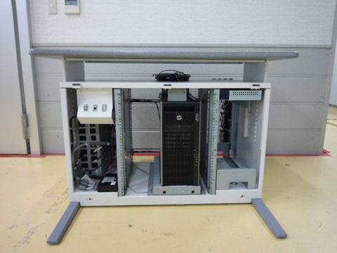
- Do not install the Keyboard Tabletop Assembly at this time.
4.3 Assemble Console Keyboard Tabletop
Procedure
- Refer to Installation - Mechanical Installation - Operator Console Installation in the Lightspeed VCT Service Manual supplied with the upgrade.
- Follow the Console Keyboard Tabletop installation instructions.
4.4 Connect Peripherals
You will receive either one of the following Peripheral Tower:
Two-bay Enclosure Type (5270510–11) or Single-bay Enclosure Type (5270510–20)
Procedure
- Connect the DVD-RW USB cable (5433899–4) to Host USB port #8.
Connect the Ext HDD USB cable (5433899–3) to Host USB port #7.
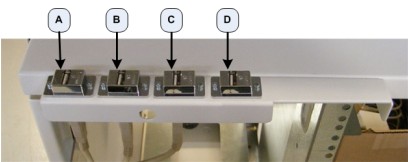
- Connect the USB Cables coming from the Host Computer into the rear of the DVD Peripheral Tower. (See Figure 3 or Figure 4)
Figure 3. DVD Peripheral Tower Connections for 5270510–11
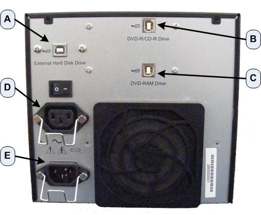
Figure 4. DVD Peripheral Tower Connections for 5270510-20 / -21

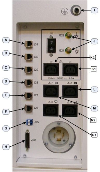
- Connect the DVD Peripheral Tower Power cable to the rear of the DVD Peripheral Tower (Item E in Figure 3 or D in Figure 4) and connect the other end of the Power Cable into the Lower Rear Bulkhead Panel. (Item L in Figure 5)
Figure 5. Lower Rear Bulkhead Panel Connections
- Connect the GSCB cables to the console according to Figure 6 and Table below.note:
Do not connect the GSCB – Black DB-25 connector (Item 7) to J20 on console rear bulkhead. It should be directly connected to TGP Gantry Cable.
Figure 6. GSCB Connections
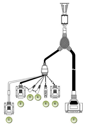
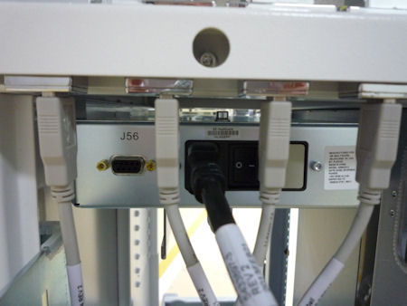
Figure 7. J56 Connector on Power Box
- Connect the Mouse to the Console by plugging the Mouse into the Upper Bulkhead Panel. (Item B in Figure 8)
Figure 8. Upper Bulkhead Panel Connections
- Connect the Keyboard to Console by passing the Keyboard USB Cable through the GSCB Assembly and plugging the Keyboard into the Upper Bulkhead Panel.
Figure 9. Keyboard Connection
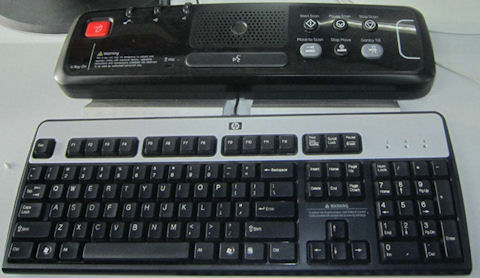
- There are three kinds of overlays in the keyboard collector: (1) with Tilt; (2) without tilt; (3) without E-Reset.
Select the without E-Reset with local language overlay film from the collector and attach it to GSCB.
Verify that none of the buttons get caught and stuck under the overlay.
4.5 Connect Accessories
Procedure
- Connect the Monitors to the Console by inserting the Video cables (Item B and C in the following Illustrations) into the Monitors coming from Host Computer.
Figure 10. EIZO S1921-X / S1923-H LCD Prescription / Image Monitor Connections
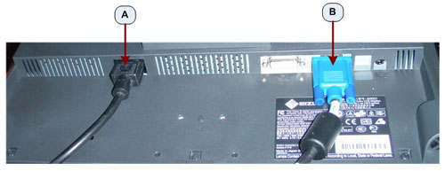
Figure 11. EIZO S1921-X / S1923-H LCD Prescription / Scan Monitor Connections
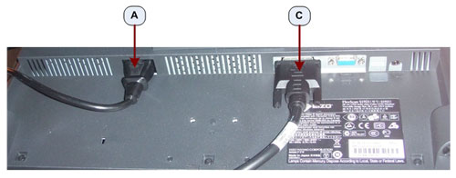
- Run the Power cables from the Monitors (Item A in the above Illustrations) to the Console’s Lower Rear Bulkhead Panel. (Item N1 and N2 in Figure 5).
- Connect the Trackball to the Console by plugging the Trackball into the Upper Rear Bulkhead Panel. (Item D in Figure 8)
- Connect the Bar Code Reader (if so equipped) to the Console by plugging the Bar Code Reader into the Upper Rear Bulkhead Panel. (Item A in Figure 8)
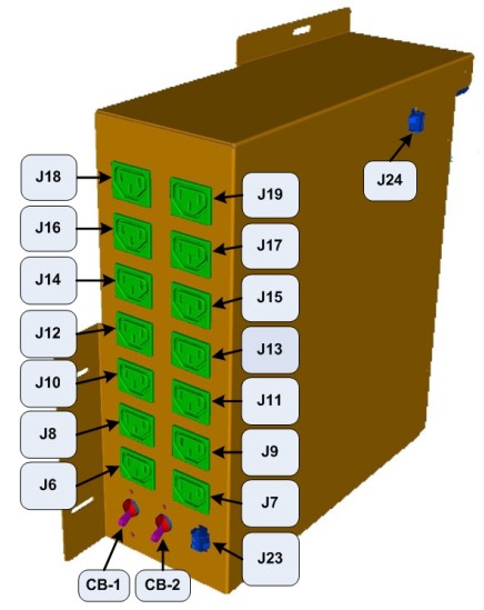
- Place and connect the Video Amp/Splitter (if so equipped). Connect the Video Amp/Splitter power cable to the Console Outlet Box J19 inside the Console.
Figure 12. Power Distribution Box
Connect the Video cable coming from the Host Computer Right Display and Right Display Monitor Video cable to the Video Amp/Splitter.
4.6 Connect Rear Bulkhead Cables
Procedure
- Reconnect the Gantry and Network Interface Cables removed earlier from the old Operator Console.
- See Figure 5 for proper connection locations.
NOTICE: IT IS IMPORTANT THAT NETWORK INTERFACES BE CORRECTLY PLUGGED INTO THEIR RESPECTIVE PORT LOCATIONS.
4.7 Connect Power and Grounds
Procedure
- Connect the Scan Room Patient Reference Ground cable to the rear of the Console. (Item I in Figure 5)
- Connect the Twist-N-lock Power Cable on the Console.
- Remove Lockout/Tagout.
Refer to Safety – Equipment Service – Lockout / Tagout - PPE in the LightSpeed VCT Service Manual supplied with the upgrade, and perform the Lockout/Tagout process in reverse.
- Power On the console and confirm that all computer connections are receiving power.note:
At this time the console may not properly initialize to full system functionality.
5 Console Initialization
Read this section in its entirety before executing this part of the procedure! In almost every case a Load From Cold will be required to complete the Console Upgrade.
5.1 Generate eLicense Key for new console
All old Software License keys from original Customer Order will no longer work for the new console. You will need to generate new license keys by eLicense
For the details of the eLicense tool, receive CT E-LICENSE TRAINING (COURSE ID: GEHC- TECH-AMOL-CT6002) in MyLearning.
You will need the following information to generate eLicence keys.
-
GON (Global Order Number) of the original customer order
-
Host ID of the new console (This can be obtained by executing check_config command)
Procedure
- Login to the eLicense web tool. (http://elicense.gehealthcare.com/elicense/)
Figure 13. eLicense - Login
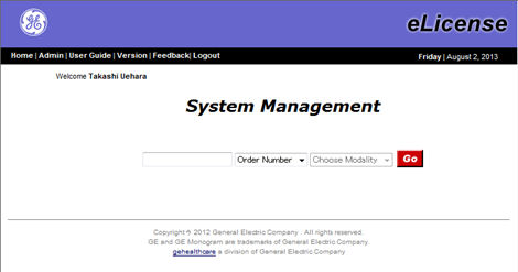
- Enter the GON (Global Order Number) of the original customer order and click “Go”. 3. The Order Assignment screen will be displayed.
Figure 14. Order Assignment Screen
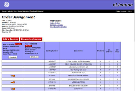
- If there is no information of the system in the top of the list, it means eLicense was never generated on this system. Register your system information by “Add a System” button. Refer to CT E-LICENSE TRAINING material for the details.
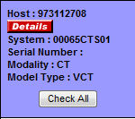
- If there is information for the system under upgrade, update the Host ID for the new console by clicking “Details” button.
Figure 15. New Host ID
- After completing the addition of the system or updating the Host ID information, generate the eLicense keys by “Generate Licenses” button.
- Click “Save Licenses” button to save the eLicense key to your laptop PC.note:
The following options are not compatible between original and new console. The eLicense tool will generate both original and new license key. Installation of the original key will be rejected by CT system.
5.2 LFC Preparations
Make note of the following LFC process clarifications.
Procedure
- Refer to DAS type as record in Section 4.2 "Identify Dectector/DAS type. LFC is required on any of DAS / Detector configuration system.
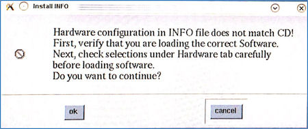
- When loading INFO file during application Software load, the following pop-up will appear.
Click OK to proceed.
Figure 16. Pop-up Window - Install INFO
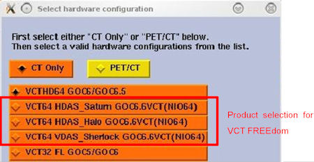
Select the appropriate hardware configuration in the hardware setting screen.
Figure 17. Hardware Setting Screen
- During the LFC process when executing the LFC Menu, skip the Install Options step. Options will be manually installed after LFC.
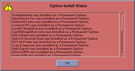
- Option install failure message will appear when Restore System State is completed because the existing option keys are not compatible with new host computer. Make sure no other errors are contained in the sysstate.log.
Figure 18. Error Message
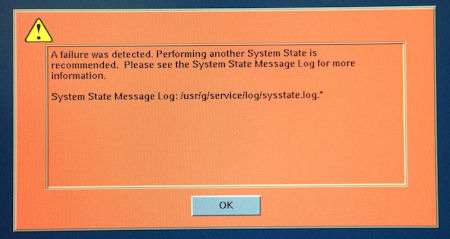 note:
note:Ignore the “The file doesn't exist.” Message in the log. This is not a failure.
5.3 Load from Cold (LFC)
Procedure
- Perform Load from Cold.
Refer to Software GOC6.6 VCT > Software Installation Procedures > (13HW31.x) GOC6 Series Load From Cold procedure in the LightSpeed VCT Service manual supplied with the upgrade.
- After completing the Restore SysState in LFC Menu, quit the LFC Menu.
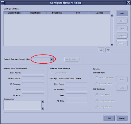
- If remote archive was previously used. Set the Default Storage Commit Host in the Network Configuration menu. This setting is not restored from system state media.
Figure 19. Window - Configure Network Hosts
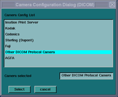
- If SmartStep and/or SmartView option will be installed on this system, perform the following procedure to prevent multiple ”No Printer Installed” pop-up messages.
- If any DICOM camera or Postscript printer will be connected to this system, no action is required. Proceed to next step.
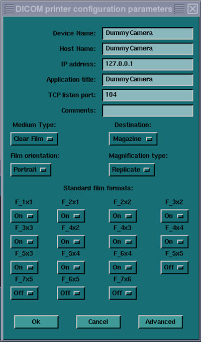
- b. If DICOM camera or Postscript printer is not planned to be connected to this system, configure a dummy camera settings in Common Service Desktop → Configuration → Install Camera.
5.4 Install Option Software
Procedure
- Install the eLicense option keys which were generated at Generate eLicense Key for new consolesection 4.5.1.note:
eLicense key can be installed either by install via USB/CD-ROM or download via InSite or manual entry. Refer to CT E-LICENSE TRAINING (COURSE ID: GEHC- TECH-AMOL-CT6002) in MyLearning for more details. The following steps explain how to install the eLicense key via USB memory.
- Copy the “license.dat” file which was generated by eLicense web tool to an USB memory mounted on your laptop PC.
- Insert the USB memory to the service USB port on the console front.
- Open a Unix shell and type mountUSB
- Type cp /USB/license.dat /usr/g/service/flex
- Type unmountUSB and remove the USB memory from the service USB port.
- Reboot the system.
-
Option key installation will be automatically started after OS is started up.
-
Some options will ask you to confirm the settings. Check or enter the appropriate parameters.
-
When all eLicense keys are installed, the following pop-up message will appear.
-
- After application start up, check that all options are installed by Verify Options in Common Service Desktop - Configuration tab.
- Install additional option keys (DVD) supplied with this upgrade kit according to Install Software Options in LightSpeed 7.X Service Methods.
5.5 Reconnect the Hospital Network Cable
Procedure
- Reconnect the Hospital Network cable at the rear of the Operator Console (J26) that was disconnected at the beginning of the LFC.
- -
5.6 Tube Install Certification
Procedure
- Perform the Tube Install Certification procedure.
- When completed, continue with Flash Download.
5.7 Flash Download
Procedure
- Perform the Flash Download Utility found on the Common Service Desktop - Utilities Tab, select [Flash Download].note:
The Flash Download takes 5 - 30 minutes, depending on which subsystems need firmware updating.
- When the Flash Download Window opens, Select [Update].
- Once the Hardware Flash Downloads successfully, select [Dismiss].
- Close the Common Service Desktop.
- Select Shutdown icon on the Desktop and restart the system.
5.8 GSCB Configuration and Intercom Set Up
Procedure
- Configure the GSCB following the GSCB Configuration and Intercom Setup procedure found in the LightSpeed 7.X Service Manual.
Refer to Align/Setup/Cal > Console (GOC6.6) > GSCB Configuration and Intercom Setup procedure.
- Setup and adjust the Intercom speaker and microphone volumes following the GSCB Configuration and Intercom Setup procedure.
Refer to Align/Setup/Cal > Console (GOC6.6) > GSCB Configuration and Intercom Setup procedure.
5.9 Install System Warning Labels
Procedure
- notice
- All labels are installed in English and present on Console. Add the labels listed below for the appropriate language for the country in which this system is installed. Additionally, apply any other warning labels if present, on equipment where appropriate.
- -
 |
5.10 InSite Checkout
Procedure
- If the InSite (and iLinq) was previously used, perform the InSite checkout here.note:
New model type (_SUSE_IIP4) is required for the checkout.
- -
6 System Level Verification Test
Procedure
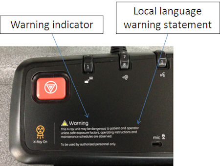
- Check the GSCB warning labels.
- Check the X-ray warning indicator is attached to the GSCB.
- Check the X-ray warning statement is in the appropriate language.
Figure 22. X-Ray Warning Label
- System Ground Checknote:
Complete the following items. Refer to the LightSpeed 7.X Installation Manual for the detailed procedure.
- Table/Gantry raceway to Console ground wire resistance should be less than 1.0 ohm.
- System Ground Chassis Leakage test was performed and the results indicate a passing condition.
- Patient Touch Leakage test was performed and the results indicate a passing condition.
- User Interface Language
Confirm that appropriate or Requested language is installed.
note:The UI is expected to be using the language appropriate for the country in which this system is installed, according to Direction 5221102-1EN. If an authorized site representative chooses another UI language, record the following information.
-
Radiology Manager (or equivalent)
-
Date of discussion
-
Language selected
-
- Check Operator Controls / Indicators
-
Check the GSCB X-ray On indicator illuminates during a scan.
-
Check the GSCB stop scan controls terminates a scan when pressed.
-
- Functional System Tests
Refer to Functional Checks - System Scanning Tests in the LightSpeed VCT Service Manual supplied with the upgrade and perform the tests to confirm proper operation.
7 Finalization
Procedure
- Reinstall the Console Front and Rear Covers.note:
Refer to Replacement > Console > GOC6.6 VCT > Console Cover Removal and Installation in the LightSpeed VCT Service Manual for more details.
- Save a new System State in accordance with Software GOC6.6 VCT > Software Installation procedures > System State Save Restore in the LightSpeed VCT Service manual supplied with the upgrade.
- The old console has components that are needed to cover FRU shortages. Return the de-installed console to GPRS Harvest team according to the procedure below.
- Material Policy Overview
-
Returned Material : Per CT GOC Upgrade commercial contract, all de-installed GOC consoles are GE property and therefore need to be returned intact and promptly to GPRS Harvest. Do not remove or swap any parts from the console, but ship the console entirely instead.
-
Disposed Material : Regulations governing the disposal of this equipment or material vary from location to location and from country to country. In order to insure compliance with all local, state, or national environment, health, and safety regulations, dispose of all items in the per local GEMS policy and procedures and other applicable published guidance. Contact GEMS Recycling Center for assistance.
-
- Harvest Steps
- Material Policy Overview