- Topic ID: id_15460638
- Version: 2.0
- Date: Nov 8, 2018 1:36:21 AM
Level the Gantry
Prerequisites
Overview
This procedure is designed for gantries that are mounted on 102 mm (4 in.) concrete floors that meet all of the pre-installation flooring requirements.
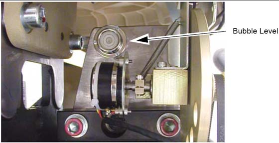
The gantry uses two (2) bubble levels that are permanently mounted to machined surfaces on the stationary base to determine when it is level.
The bubble levels are located on both ends of the gantry stationary base near a point where the rotating structure pivot-mounts to the base structure. (See Figure 1.)
Figure 1. Gantry Bubble Level
Procedure
- Loosen all adjuster lock rings (use a spanner wrench or large tongue and groove pliers).
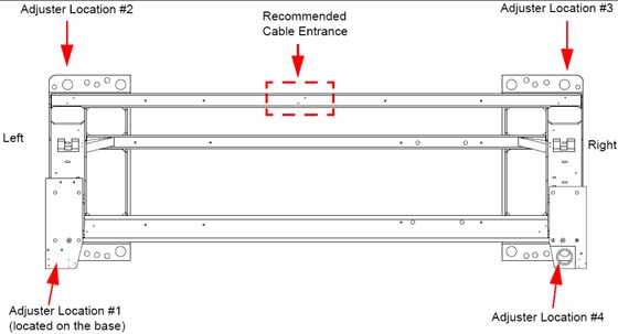
- Systematically turn each of the gantry’s adjusters (locations
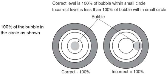
1, 2, 3 and 4 in Figure 3) until both bubble levels are centered left-to-right
and front-to-back (see Figure 2).
- Begin by turning each adjuster no more than 1 turn at a time.
- Use the adjuster tool, 1-1/8 in. socket, and the ½ in. drive ratchet to turn each adjuster. (Refer to Figure 2.)
- Level the left side from front-to-back by turning adjusters #1 and #2.
- Level the right side from front-to-back by turning adjusters #3 and #4.
- Level the side (right or left) that is higher with respect to the other side. Turn both adjusters on a side equally until that side is level. The side should now also be level.
Figure 2. Bubble Level Centering
 note:
note:Gantry level is critical to system operation!
- When the bubble levels are centered (Figure 2), each of the
four (4) leveling pads should be carrying a portion of the gantry
weight. Distribution of the gantry weight prevents the base frame
from rocking during normal operation.note:
The bottom of the gantry base must be at least 2.0 cm (3/4") above the floor to ensure that the base covers fit. Measure at all four corners and if any corner is to low, then the gantry will need to be raised.
Figure 3. Gantry Base Adjuster Locations — Top View
 caution
- If there are floor obstructions, such as conduits or old anchors, be sure to cut them flush to the floor to prevent the gantry from resting on them. Also, be sure there is at least 102 mm (4 in.) of distance from any existing floor penetration to the new gantry anchor positions.
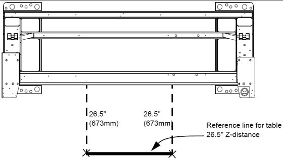
- Using a measuring tape, measure and mark two spots 673 mm (26.5 in.) from the gantry base frame (under the front cable tray) out toward the table floor cutouts, as illustrated by X marks at the bottom of the dotted lines in Figure 4.
- Snap a chalk line using the two 673 mm (26.5 in.) marks. This
line should be parallel to the gantry and 673 mm (26.5 in.) from the
front of the gantry base. See Figure 4. In a later
section, you will move the table against the 673 mm (26.5 in.) mark
and center it over a table center line (to be drawn at that time.)
Figure 4. Table Base Reference Line and Marks
 |
Finalization
No finalization steps.