- Topic ID: id_15460637
- Version: 2.0
- Date: Nov 8, 2018 1:36:21 AM
Move Gantry into Final Position
Prerequisites
1 Gantry Preparation
Locate and install any required floor protection now.
1.1 Access Greater than 28 in.
Procedure
- Remove all the transportation packaging from the gantry, except for the dollies.
-
1.2 Access Less than 28 in.
Measure from the wall or object protruding from the wall to the gantry side cover. The gantry left side cover must be installed for this measurement. When finished, the gantry cannot be closer than 14 in. to the wall or object protruding from the wall.
Procedure
- Remove all the transportation packaging from the gantry, except for the dollies.
- Remove the blue dolly from the left side of the gantry and install
the limited access dolly so that the gantry can be positioned closer
to the left side wall.
- Remove the three (3) M14 hex bolts that secure the gantry to the dolly.
- Replace the removed dolly with the shipped black gantry-positioning dolly, and reinstall the three (3) M14 hex bolts.
- Raise the gantry so that it is once again off of the floor.
The gantry can now be moved up to 14 in. from the wall, measured from the wall or object protruding from the wall to the gantry side cover. Only use the supplied, limited-access dolly for this procedure.
note:If this procedure cannot be completed, follow the site escalation procedure established for your area.
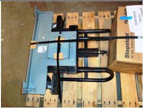
Figure 1. No Name or Figure Number
2 Gantry Installation
Procedure
- Position the gantry over the floor cutouts appropriately.
- Locate the four (4) leveling pads, and position each beneath its associated adjuster. A ½ in., ratchet and 1-½ in. socket are required to loosen the gantry shipping bolts.
- Use the dollies to evenly lower the gantry, until it is just off of the floor (approximately ¾ in. or 20 mm). Use a ½ in. ratchet to raise and lower the dollies.
- Carefully rotate the gantry into the correct position over cutouts in the floor.
- Use floor protection as appropriate.
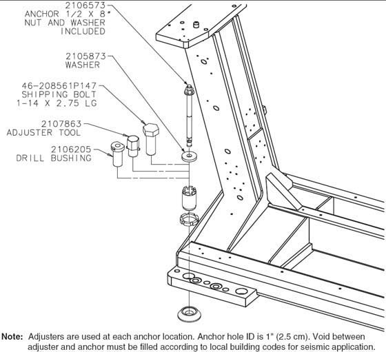
Figure 2. Gantry Base Installation Hardware
- Loosen the locking rings with the spanner tool. Turn gantry levelers by hand until each leveler is down 1/2 in.(13 mm) from the bottom of the gantry frame.
- Leave the locking rings loose so you can fine-tune the leveling pads to compensate for slight variations in the floor surface.
- Position the gantry so that the adjusters are centered over
their respective holes marked earlier into the floor cutouts.note:
Due to the large plug head size, it may be easier to route the gantry 3-phase power cord under the rear gantry rails before lowering the gantry. If not, feed it from the PDU side of the cable. (This cable can be found on the Lean Cart with the power cables.) Also, due to the ferrite cord on cables Run 100 and Run 101, it may be easier to route these cable at this time. Do not crush cable under equipment.
- Using a ½ in. ratchet, gently lower the gantry until
it rests on the floor over the marked areas. When finished, the gantry
should now be resting on all four leveling pads.
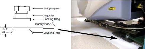
Figure 3. Gantry and Table Base Leveling Pads (Starting Positions)
- notice
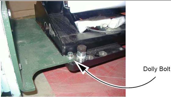
- Using a 14 mm hex socket, remove the dollies from the gantry
by removing the three dolly bolts found at both ends of the gantry
(Figure 4).
Figure 4. Gantry Dolly Bolts
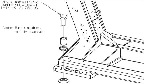
- Remove the four (4) gantry shipping bolts, using a 1½
in. socket.
Figure 5. Gantry Shipping Bolts
 |
Finalization
No finalization steps.