- Topic ID: id_15460504
- Version: 2.0
- Date: Nov 8, 2018 1:36:39 AM
LS VCT Gantry Options Interface Upgrade Procedure
Prerequisites
Overview
This procedure describes the steps necessary to upgrade the gantry with the Integrated Peripheral controller assembly and cabling. The IPC is a new version of the Gantry Options Board (GOB) for use on all VCT platforms.
1 Preparation for Upgrade
Procedure
- notice
- Make sure all parts have been delivered in the kit per the contents list to avoid partial install issues. Reference Step 3 for parts list.
- Remove gantry right side cover and disable Axial drive, HVDC
and 120VAC service switches from the Service Switch Panel.
Refer to
- Remove the Gantry left side, top, front and rear covers. Connect the cover E-stop circuit to the terminators on the gantry.
- Remove all Gantry Base Covers. Cover on the bottom of the tilting assembly can stay in place. The side base covers can be discarded as they will be replaced with new side covers with cutouts for the interface panels.
- Remove the gantry lower cantrells (latches) for the rear cover to avoid potential damage during gantry tilt steps.
- Tilt the gantry all the way back for easier access to gantry
base from the rear using the following steps.
-
Turn on the gantry 120VAC service switch and press the table drives enable at the lower right corner of the service switch panel.
-
Turn on service mode switch S4 (up position)
-
Turn on the tilt enable switch S9 (on position)
-
Use the tilt switch S10 to tilt the gantry all the way back to the tilt stop blocks. Check clearances on both sides when getting close to full back to make sure there are no obstructions that need to be cleared.
-
Turn off the gantry 120VAC service switch.
-
- Shut down the console and perform LOTO for the gantry per safety procedures.
- Open the attached PDF file for easy reference in the next sections.
This drawing shows the overview of the parts being installed.
Figure 1. Options panel upgrade kit drawing
5323525INS.pdf
 |
2 Ethernet switch assembly installation
Procedure
- From the supplied 1” wide velcro strips cut the following:
-
Cut 2 strips (hook and loop pair) 100mm (4 inch) long for the Ethernet switch
-
Cut 1 strip (hook and loop pair) 75mm (3 inch) long for the power supply
-
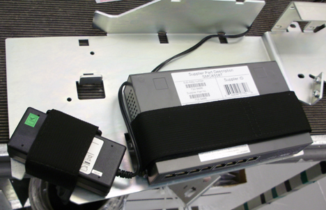
- Attach the hook side of the velcro strips to the Ethernet switch
and power supply and mount to new plate as shown in Figure 2 and Figure 3.
With the loop side of the velcro attached to the hook side remove the protective strip over the adhesive and mount the Ethernet switch and power supply to the mount plate such that each part is centered between the hole and cutout in the plate for each of the two components. The port side of the Ethernet switch should line up with the edge of the plate.
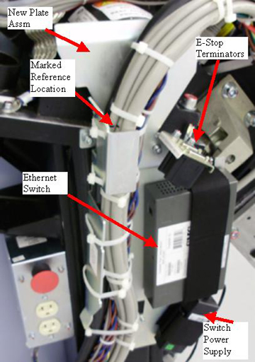
Figure 2. Velcro installation
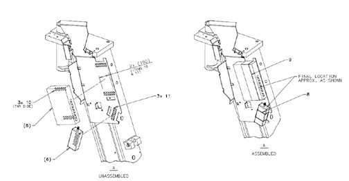
Figure 3. Component locations
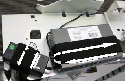
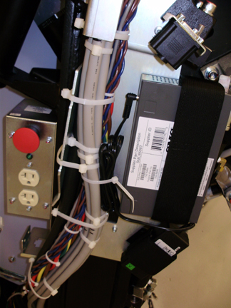
- Route the two velcro straps around the plate, through the cutout
and around the Ethernet switch and power supply individually. The
end of the strap folded back on itself should be on the front side
of the each part. Reference Figure 4
Figure 4. Velcro Strap Routing
- Place a mark on the cable bundle above and or below the top
cable tie plate for the gantry cable harness for reference when positioning
the harness on the new plate. Clip the cable ties holding the gantry
cable harness to the current cable tie brackets. Reference Figure 5.
Figure 5. Gantry cable harness
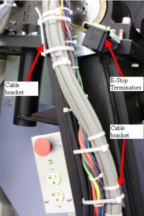
- Remove the E-stop terminator plate assembly from the gantry (2 screws, 5 mm hex wrench). Reference Figure 5.
- Remove the 2 cable tie brackets (3 and 5 mm hex wrenches) from the gantry leg and discard. Reference Figure 5.
- Mount the new bracket assembly with Ethernet switch and power
supply to the gantry leg using the supplied M6 and M4 screws (2 each,
3 and 5 mm hex wrenches), lock washer and washers and using loctite
242.
Figure 6. New bracket assembly
- Install the E-stop terminator assembly (reference Figure 6) onto the new
bracket (5 mm hex wrench) and torque to:
- Position the gantry cable harness in the new bracket using the marks placed on the cable bundle to position the bundle then use cable ties to strap the bundle in place. Reference Figure 6.
- Connect the power line from the Ethernet power supply to the
switch and bundle the extra length of power line to the gantry harness.
Reference Figure 7.
Figure 7. Ethernet power line routing
3 Emergency Stop/Service Outlet Plate and cabling upgrade
Procedure
- Remove the E-stop button and outlet plate assembly. (4 screws
using 3 mm hex wrench)
Figure 8. E-Stop and outlet box modification
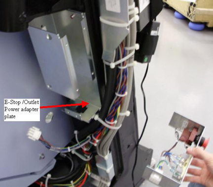
- Remove 2 screws (3 mm hex wrench) holding outlet box to the gantry leg.
- Place power cable adapter plate behind outlet box and reinstall on gantry leg using the 2 M4 screws removed above (3 mm hex wrench) and hand tighten.
- Install E-Stop and service outlet plate into box using the 4
M4 screws previously removed. (3 mm hex wrench)
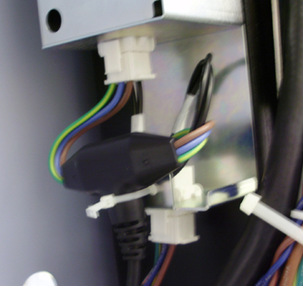
- Insert “Y” power adapter cable bulkhead connector
into power cable adapter plate and connect power cabling to the new
adapter cable. Use cable ties as shown in Figure 9.
Figure 9. Power Adapter
4 IPC Panel and power box installation
4.1 Gantry right side (service switch side)
Procedure
- Assemble right panel to right side mount bracket using M4 lock
washers and nuts for the 2 studs from the panel and hand tighten.note:
may need to shift the pre-mounted ground wire to fit the panel into the bracket.
Figure 10. Parts
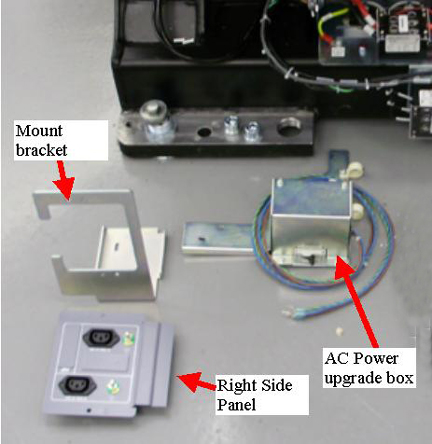
- Mount the Power upgrade box to the gantry frame as follows.
- Position the box as shown in Figure 11. The plastic
cable clamps are for the Ethernet, fiber, and power lines.
Figure 11. Power box mounting
- The rear plate mount point will be fastened by velcro as follows:
-
Cut a piece of velcro (from the pieces left over after installing the ethernet switch assembly), approximately 1 inch or 2.5 cm square.
-
Remove the covers over the adhesive and place the velcro between the bracket and the gantry to hold the bracket in place. This mount location does not affect the structure but having velcro here will ensure there are no vibrations that will cause a noise from the bracket if it is not attached.
-
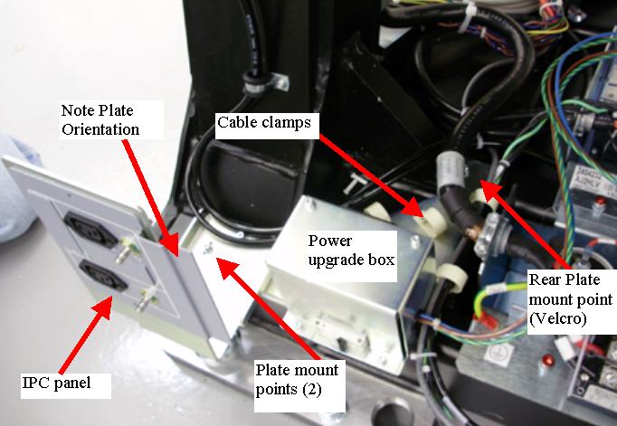
- Position the box as shown in Figure 11. The plastic
cable clamps are for the Ethernet, fiber, and power lines.
- Install the interface panel mount plate on top of the power
assembly bracket, seen in Figure 11. Center the screws in the slot. Adjustment to
base covers will be done later. Mount to the frame with 2 M4x12 screws
with lock and flat washers (3 mm hex wrench). Torque to:
- Put Hydraulic lines from the tilt piston into the supplied clamps.
Route the power cables, Ethernet and fiber cabling as shown in Figure 12.
Figure 12. Cable routing
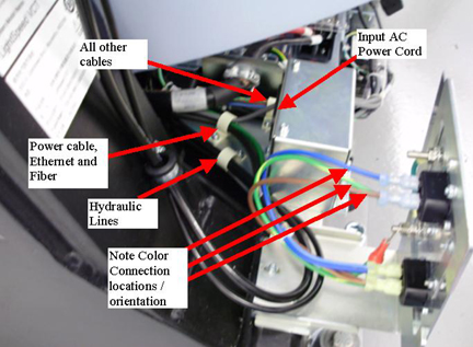
- Plug in the AC power cord to the power box and install the AC lines from the new harness into the interface panel as shown in Figure 12. Note the AC power connection to the Interface Panel Outlets for color and terminal locations (Blue to N terminal, Brown to L terminal, and Green to the Gnd). The other end of the cables will be routed to their destinations later.
4.2 Gantry left side (TGPU side)
Procedure
- Assemble left interface panel to left side mount bracket using
M4 lock washers and nuts for the 2 studs from the panel and hand tighten.
Reference Figure 13 and Figure 14.note:
May need to shift the pre-mounted ground wire to fit the panel into the bracket.
Figure 13. Parts
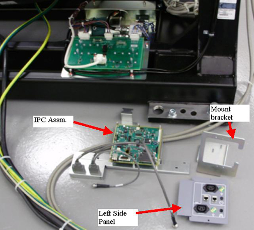
Figure 14. IPC and Interface panel mounted
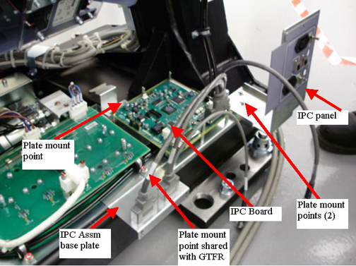
- Remove the M6 screw from the GTFR assembly mounting. (5 mm hex wrench)
- Position the IPC assembly over top of the hydraulic lines and
the IPC mount panel between the hydraulic cable clamp and GTFR base
plate as shown in Figure 14 and continue with the following steps.
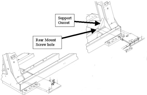
- If the assembly does not fit due to interference with the support
gusset shown in Figure 15 then the alternate IPC assembly base plate will
need to be used. Perform Step 4 to change to the alternate IPC assembly base
plate and do NOT continue with this step.
Figure 15. Gantry mount hole locations
- Install an M4 screw (3 mm hex wrench) with lock and flat washer
through the IPC mount plate into the rear hole by the gantry gusset
and torque to the values shown in Table 12.
- If the assembly does not fit due to interference with the support
gusset shown in Figure 15 then the alternate IPC assembly base plate will
need to be used. Perform Step 4 to change to the alternate IPC assembly base
plate and do NOT continue with this step.
- Perform this step ONLY if you need to
change to the alternate IPC base plate as identified in Step 3.
- Remove the cable and clear cover (4 mm wrench for cover screws) from the IPC board assembly.
- Remove the 6 standoffs holding the IPC board to the base plate
and install it on the alternate base place supplied with the kit using
the 6 standoffs.
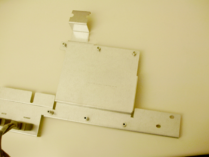
Figure 16. Example alternate base plate
- Using a 5 mm hex driver or small wrench, remove the Cardiac and Pulmonary cables from the base plate and install in the same locations on the alternate plate. Make sure to keep all hardware in same order as removed.
- Reconnect the cable and reinstall the plastic cover onto the IPC board.
- Position the IPC assembly over top of the hydraulic lines and the IPC mount panel between the hydraulic cable clamp and GTFR base plate as shown in Figure 14.
- Perform the following steps to use velcro to fasten the IPC
assembly rear mount to the gantry to avoid any vibrational noise during
system use.
-
Cut a piece of velcro (from the pieces left over after installing the ethernet switch assembly), approximately 1 inch or 2.5 cm square.
-
Remove the covers over the adhesive and place the velcro between the bracket and the gantry to hold the bracket in place. This mount location does not affect the structure but having velcro here will ensure there are no vibrations that will cause a noise from the bracket if it is not attached.
-
- Reinstall the M6 screw (5 mm hex wrench) with lock and flat
washers. Torque to:
- Position the interface panel assembly on top of the IPC base plate with 2 M4 screws (3 mm hex wrench) with flat and lock washers and hand tighten.
- Install the cardiac lemo feed through plug to the port with
the heart symbol port on the panel. Position such that the nut on
the outside of the panel is threaded down flush with the threads.
tighten the rear nut to secure the feed through. Repeat for the Respiratory
feed through for the lung symbol port. Reference Figure 17 and Figure 18.
Figure 17. Lemo Installation Side View
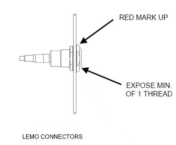
Figure 18. Lemo feed through installation

5 Cable installation and routing
Procedure
- Connect the E-Stop cables for front and rear covers to the terminator plugs on the gantry frame.
- Remove LOTO to allow the gantry to power up. Apply power to the gantry. Turn on the 120 VAC service switch and press the table drive reset button.
- Using the Tilt switch (S10), tilt the gantry forward to have easy access to the cable tray along the front base of the gantry.
 danger
- Turn off the 120 VAC service switch and disable power to gantry using LOTO.
- Layout the remaining cabling in front of the gantry. Look at
the labels on the ends to identify which end goes on which side of
the gantry. Specific position will be covered in the following steps.note:
When feeding cables to the left and right sides of the gantry in later steps, feeding the cables under the cable clamps will save time instead of removing and reinstalling the clamps if space allows.
Figure 19. Gantry cable tray
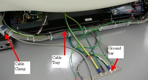 note:
note:Open the following cable harness drawing as a reference when installing the cable harness. The drawing shows the cables and connection locations as well as harness location with respect to the gantry cable clamps shown above.
Figure 20. Cable Harness drawing
Cable bundle map.pdf - For the cable harness, the 2 ground wires should be positioned in the left/right center of the gantry to feed straight out to the ground bar under the foot/switch. This is the starting position to then route the rest of the harness following the existing gantry cable pathways to the respective locations.
- Route the cables to their defined locations shown in Figure 20 with the following
guidelines.
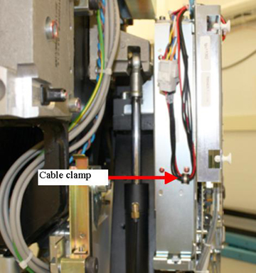
- Install the TGPU power tap off cable and Install cable clamp
behind TGPU to hold power harness. Reference Figure 21.
Figure 21. TGPU power tap off cable
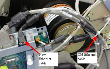
- When installing the new Ethernet cable to the TGPU use a cable
tie to tie back the existing Ethernet cable end at the TGPU and then
plug in the new Ethernet connection. Use this same cable tie idea
when connecting the new Ethernet cable at the gantry input (rear base
of gantry by power input).
Figure 22. Ethernet connection
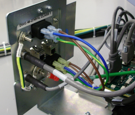
- Connect the power cable lugs to the outlet as shown in Figure 23. Note the AC
power connection to the Interface Panel Outlets for color and terminal
locations (Blue to N terminal, Brown to L terminal, and Green to the
Gnd).
Figure 23. Power connections example
- For the three (3) Ethernet cables going to the Ethernet switch, route them under the velcro strap holding the switch to keep them in place.
- Install the TGPU power tap off cable and Install cable clamp
behind TGPU to hold power harness. Reference Figure 21.
- Starting at the center of the gantry cable path, cable tie the new cables to the existing gantry cable bundles working from to each side to the gantry. Remove existing cable ties and install new cable ties at each cable tie bracket on the gantry frame.
- The gantry to injector cable (5169456) included in the kit runs from the Sub-D connector by the IPC panel to the Injector.
 |
6 Connect power lines to the Power Pan
This section defines the connection between the power upgrade box and the existing power pan.
Procedure
- Remove the plastic cover from the top of the power pan by 2
- M4's (3 mm hex wrench).
Figure 24. Power Pan AC filter
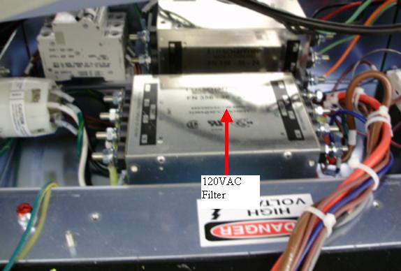
- Route the power line from the power upgrade box into the power
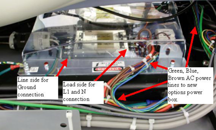
pan. On the 120 VAC line filter, connect the lugs as follows:
Connect the wire lugs under the washer and lock washer. Tighten the nuts making sure all preexisting lugs are still connected.
Figure 25. Power line connections
- Reinstall the plastic cover over the power pan with the 2 - M4's (3 mm hex wrench). Snug the screws being careful not to crack the plastic cover.
- Inspect the cable runs and finish installing any cable ties to keep cable bundles together.
7 Power on checks
Procedure
- Before turning on power, turn off CB4 on the new power upgrade box.
- Remove LOTO and power on the gantry.
- Now turn on CB4 on the new power upgrade box.
- danger
- Using a digital voltmeter, check each of the 4 outlets, 2 on
each interface panel to make sure 120VAC is seen.
If no power is seen shut down gantry power. Perform LOTO to remove power to gantry. Recheck power cabling connections for the new power box.
Restore power and repeat this step.
- While watching the gantry cabling, tilt the gantry forward and backward using the service switch panel Tilt switch S10. (Service Mode S4 is up and Tilt Enable S9 is ON) to make sure there is no cable interference with tilt function and there are no cables being pulled or rubbed during tilt function.
- Leave the gantry in a zero tilt position. Turn Tilt Enable S9 to Off and put the Service Mode switch in the down position.
- Turn off the gantry using the 120 VAC service switch.
|
8 Reassembly gantry
Procedure
- Install the gantry base covers including the 2 new side base
covers with the cutouts for the interface panels.
Refer to
note:When putting on the rear base covers you may need to adjust the IPC panels such that the base cover can be fully installed. Adjust panels in or out as necessary.
- Install the gantry lower rear cantrells (latches) for the gantry rear cover attachment.
- Install the gantry front and rear covers, scan window, then the top and left side covers.
- Turn on the 120 VAC, Axial drive and HVDC service switches from the Service Switch Panel.
- Install the gantry right side cover.
- Add the upgrade rating plate to the gantry left leg near the other rating plates.
9 Finalization
Procedure
- Run the System scanning test from the Functional Checks procedure list.
- Plug in any options the customer has to the interface panels as applicable for your site. Perform any defined functional checks for the options plugged into the interface panels.
- Below is a kit contents listing for reference purposes.