- Topic ID: id_15460678
- Version: 3.0
- Date: Jun 15, 2020 11:00:58 PM
ICOM Replacement
Prerequisites
Overview
This procedure describes and illustrates the steps necessary to replace the ICOM Assembly.
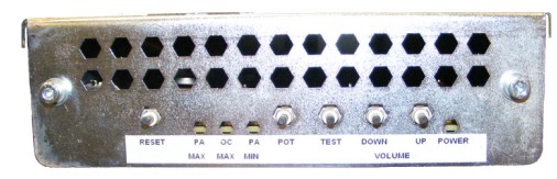
Figure 1. ICOM Assembly
1 Power-Off (Shut Down) the Console
Procedure
- Select one of the following methods to power off the Operator
Console:
-
If applications are running, click the Shut Down icon and select Shut Down.
-
If applications are down, open a Unix Shell using the Toolchest.
Type: {ctuser@hostname} halt. Press Enter.
The Operator Console monitor will display a ‘System Halted’ message when it is acceptable to power off the Operator Console.
-
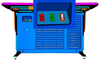
- Power OFF the Operator Console at the front panel switch. (See Figure 2.)
Figure 2. Console Power Switch
- Perform prescribed Lockout/Tagout procedure. For added protection, disconnect the Twist-N-Lock Main Power Cable from the rear of the console.
2 Remove Old ICOM Assembly
Procedure
- Remove the front and rear Operator Console Covers per prescribed cover removal procedure.
- Remove the USB cables connected to the underside of the Upper Bulkhead Panel to allow removal of the ICOM Assembly.
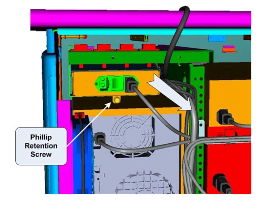
- At the rear of the console, loosen the Phillips Retention Screw
holding the ICOM assembly to its support bracket.
Figure 3. ICOM Mounting
- Carefully pull the ICOM Assembly out the back of the operator
console.note:
Cables will still be attached on the side of the ICOM Assembly. Take care not to catch these cables and their connectors on the support bracket.
- Remove the power cord from the rear of the ICOM Assembly.
- Remove all cable connections from the ICOM Assembly. note:
Verify that all cables are labeled and clearly marked; if necessary, add a label for clarity.
- Now free of cables, set old ICOM Assembly aside.
3 Install Replacement ICOM Assembly
Procedure
- Connect cables removed earlier onto the new ICOM Assembly.
Figure 4. ICOM Assembly Connections & Destination
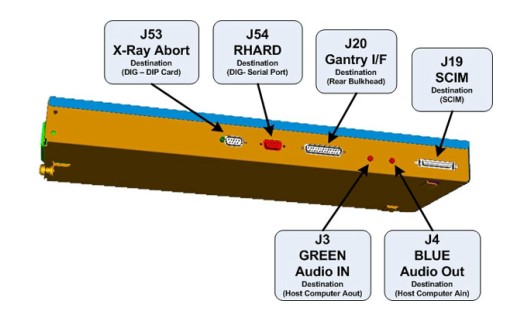 note:
note:For cabling details, refer to the appropriate interconnect located in the System Diagrams folder of this service methods publication.
- Re-attach the power cord at the rear of the ICOM Assembly and make sure the power switch is tuned on.
- Carefully slide the new ICOM Assembly back into the console
from the rear side.note:
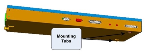
Make sure that the ICOM Assembly mounting tabs on the bottom of the assembly catches on the support bracket.
Figure 5. ICOM Mounting Tabs
- Tighten Phillips Retention Screw at the back of the ICOM Assembly to the support bracket.
- Reconnect USB cables to the underside of the Upper Bulkhead Panel. Make sure to connect the appropriate USB cables to each of the Upper Bulkhead Panel connectors. For cabling details, refer to the appropriate interconnect located in the System Diagrams folder of this service methods publication.
4 Power-On the Operator Console
Procedure
- Reconnect the Twist-N-Lock Main Power Cable from rear of console and remove Lockout Tagout protection applied earlier.
- Power ON the Operator Console at the console front panel switch.
5 Verify Replacement ICOM Assembly Operation
Procedure
- Visually verify the ICOM Assembly Power LED is illuminated.
- In order to assure proper operation of the ICOM Assembly it
is necessary to perform Intercom Setup Calibrations.
Return to this procedure when finished.
6 Finalization
Procedure
- After completing the ICOM Assembly Setup Procedure, perform a complete shutdown of the Operator Console and restart the system.
- Refer to SCIM and ICOM Functional Checks to confirm proper operation.
- Reinstall Console Front and Rear Covers.