- Topic ID: id_15460099
- Version: 3.0
- Date: Sep 30, 2019 9:32:08 PM
Hydraulic Tilt Motor Assembly Replacement
Prerequisites
Overview
This procedure defines the steps necessary to replace the tilt motor assembly.
1 Hydraulic Tilt Motor Assembly Removal
Procedure
 danger
- To proceed, inspect the replacement gantry tilt hydraulic unit and hydraulic cylinders for any damage in shipment. There should be no leaking oil and no residual oil in the shipping crate. The hydraulic pistons should be fully compressed into their cylinders. (Do not extend the pistons by hand.)
- If you suspect that the replacement unit is not in proper condition for installation or appears damaged in any way stop the replacement process and escalate by calling Field Leadership for further direction.
- If you do not see any damage remove the replacement unit from its shipping crate being careful not to kink the hydraulic lines.
- Move the table to it's full out and up position to allow full gantry tilt functionality during this procedure.note:
Spatial orientation defined in this section and for all procedures is from the perspective of an observer standing at the end of the patient table looking towards the Gantry Display board, through the gantry. This orientation defines a "Negative or minus "-") gantry position which places the top of the gantry leaning away from the observer. If necessary, refer to System Safety Overview for exact orientation.
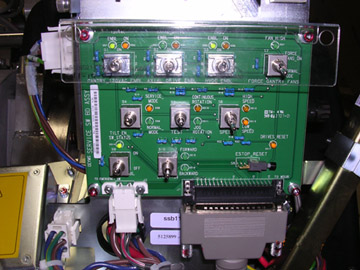
- Remove the gantry right side cover and disable 120VAC, Axial Drive and HVDC on the Service Switch Panel. See Figure 3 if necessary for service switch panel illustration.
Refer to
- Remove gantry left side, top, rear and base covers. Tilt Hydraulic Assembly is located in the base of the gantry.
Remember to connect the cable with the E-stop circuit to the gantry terminator. Only one cover cable with connect to the terminators so they can not be confused.
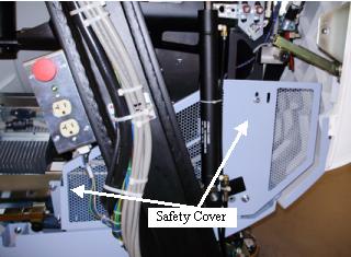
- Remove the left and right safety covers from the both sides of the gantry. These are the covers attached to the tilting assembly attached to the bottom.
Figure 1. Gantry Safety cover
- danger
- To proceed:
- If there is NOT sufficient pressure in the system to tilt the gantry all the way back to its resting position on the mechanical stops and the Safety Brackets are still installed (Gantry at zero (0) degrees):
-
Shut the system down and perform LOTO at the A1 Mains Disconnect panel.
-
Remove both side covers, any top Covers/fans and the Rear Cover. If necessary, refer to Parts Replacement→Gantry→Enclosure→(Cover Removal Procedures).
-
Locate the Tilt Locking Brackets (Yellow Shipping Brackets) on the left and right side of the gantry. Using a 10mm and 14mm Hex wrench, make sure the bolts on these brackets are in place and have not loosened up during gantry transport. Tighten them if necessary.
-
Proceed to Step 7.
-
- If enough hydraulic pressure exists in the system to tilt the gantry all the way back to its resting position on the mechanical stops:
-
Remove the rear cover bottom cantrell brackets (rear cover bottom latches). Failure to remove these brackets can cause damage to them during gantry tilt as they will hit the gantry stationary leg and bend or limit tilt when tilting all the way back
-
Power on the 120VAC switch on the service switch panel. Enable table drives from the push button on the lower right of the service switch panel.

- danger
-
From the Service Switch Panel, turn ON the Service Mode and Tilt Enable switches. Use the Tilt switch (S10) to tilt the gantry Backward until it stops at the mechanical stops. Refer to Figure 2 for a side view example of the gantry position.
note:Do NOT use the cover panel controls as they will NOT tilt the gantry all the way to the stop blocks.
Figure 2. Service Orientation for Gantry Tilt
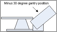
Figure 3. Service Switch Panel
-
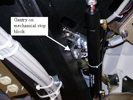
Verify the gantry is tilted all the way back and resting on the mechanical stops.
Figure 4. Gantry on stop block
-
Turn OFF the Tilt Enable, Service Mode and 120 VAC switches on the Service Switch Panel.
-
- If there is NOT sufficient pressure in the system to tilt the gantry all the way back to its resting position on the mechanical stops and the Safety Brackets are still installed (Gantry at zero (0) degrees):
- Shutdown system software and turn off the console power switch under the console table top.
- Remove all system power at the main disconnect (A1) panel. Perform proper Lockout/Tagout power control procedures.
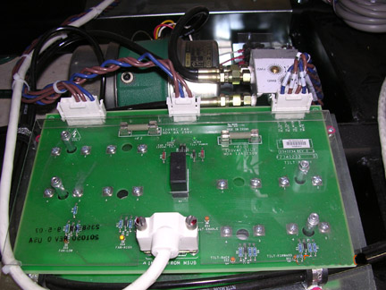
- While viewing the gantry from the rear, the gantry Tilt Hydraulic Assembly is located inside the right gantry base assembly of the gantry. Label the wires located on the gantry Tilt Relay Board for later assembly if not already labeled.
Figure 5. Tilt Hydraulic Assembly
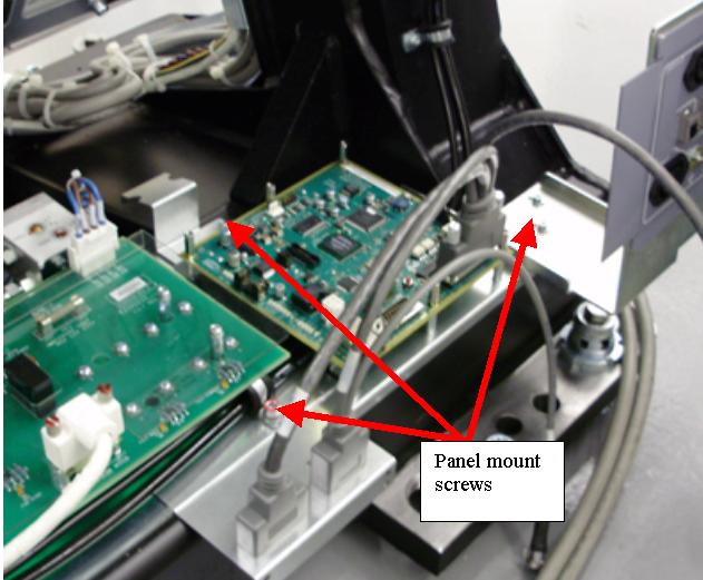
- Loosen and pull the gantry IPC board mounting bracket away far enough to allow the tilt assembly to be removed. As shown in Figure 6 the IPC bracket overlaps the tilt assembly bracket.
Figure 6. IPC panel mount screws
- While viewing the gantry from the rear, disconnect the three-phase power plug at the side of the gantry power pan, located inside the left side of the gantry base assembly.
- Remove the rear screws securing the gantry Tilt Hydraulic Assembly to the gantry base frame.
- Loosen the front screws securing the gantry Tilt Hydraulic Assembly. Their complete removal is not necessary.
- Disconnect and remove the cables connections and wires at the terminal on the Tilt Relay Board.
- Identify all tie wraps and fasteners securing the hydraulic lines to the gantry frame and Take note of the routing of these hydraulic lines.
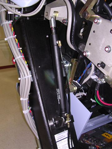
- Remove any fasteners and tie wraps securing the hydraulic lines to the gantry base frame and hydraulic cylinder. Be careful not to puncture or kink any of the hydraulic lines
Figure 7. Tilt Hydraulic Cylinder
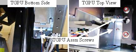
- Remove the TGPU Assembly to gain access to the left side hydraulic cylinder mount bolts.
Figure 8. TGPU Mount
- Remove both hydraulic cylinders using the following process.
- Loosen but do not remove the 4 hex socket screws at the top of the left hydraulic cylinder mount bracket. Keep your hands clear of potential gantry pinch points at all times. See Figure 7.
- Remove the spring clip from the pin holding the bottom of the cylinder. Push the pin out from the inside of the gantry toward the outside to release the bottom of the cylinder from the gantry. See Figure 9.
Figure 9. Cylinder Bottom Mount
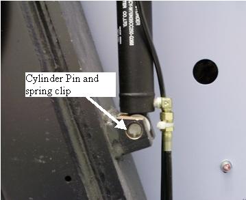
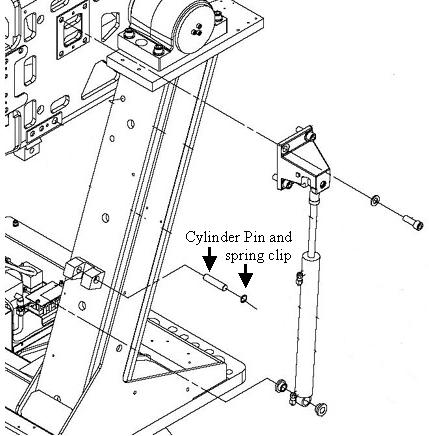
Figure 10. Drawing example
- Remove the 4 hex socket screws at the top to release the entire cylinder from the gantry.
- Remove the hydraulic cylinder and its lines from the gantry base.
- Repeat for the other hydraulic cylinder.
- Completely remove the gantry Tilt Hydraulic Pump Assembly from the gantry base.
2 Hydraulic Tilt Motor Assembly Installation
Procedure
- To proceed:
- If the Gantry is resting on its mechanical stops (all the way back), proceed with Step 2.
- If the Gantry is at Zero (0) degrees and the safety brackets are installed, proceed to Hydraulic Tilt Motor Assembly Installation: Gantry at Zero Degrees.
- Move the replacement unit to the back of the gantry.
- Install the gantry Tilt Motor Assembly into the base. Secure the gantry Tilt Motor Assembly with its four screws.
- Install the new hydraulic cylinders using the following steps. Make sure the hydraulic lines are properly routed along the gantry frame.
- Position the hydraulic cylinder, apply Loctite 242 to the 4 (four) M12 screws and install the top bracket but do not tighten yet.
- Position the bottom of the hydraulic cylinder in the bottom gantry mount and install the pin from the outside of the gantry frame.
- Install the spring clip in to keep the pin in place. Reference Figure 11.
Figure 11. Cylinder pin and spring clip
- Repeat for other hydraulic cylinder.
- Loosely secure all hydraulic lines with tie wraps. Do not tighten the tie-wraps at this time. Make sure to leave approximately 1 inch (2.5 cm) of slack on both left and right cylinder lines at the cylinder to prevent hose damage during forward tilt.
- Attach all wires and cables removed from the gantry Tilt Relay Board.
- Torque the M12 screws for the upper left cylinder mount bracket to the values shown in Table 7.
- Torque the M12 screws for the upper right cylinder bracket to the values shown in Table 7.
- Install the TGPU Assembly to the gantry frame. If any tie wraps were removed from the cables, re-install new ones. Attach any cables removed.
- Install the IPC board mounting bracket and interface panel using the same screws previously removed. See Figure 6 for screw location reference.
- Remove Lockout/Tagout following all Lockout/Tagout procedures to restore main power and restore power to the Gantry, Table and Console.
- danger
- Enable the gantry tilt function, High voltage, and 120VAC service switches from the service switch panel and press the table drives reset.
- Place the Service Switch S4 in the “Service Mode” Position.
- Make sure the Tilt Enable switch S9 is enabled.
- Use the manual tilt switch S10 to drive the gantry off of its stops approximately 1 inch (2.5cm).
- Set the Service Switch S4 to the “Normal Mode” position and Tilt Enable switch S9 to “OFF”.
- Turn on the Console using the power switch under the console table top. The system software should automatically boot the system up to full operation.
-
(For 1 FE only) If another Field Engineer is not present to aid in the initial movement of the gantry, proceed as follows. When moving the gantry tilt for the first time periodically stop titling the gantry and check the gantry movement for obstructions and slack in the hydraulic lines.
- Stand at the side of the gantry (clear of tilt motion) and use one of the operators control panels on the front of the gantry to tilt the gantry forward using the tilt feature to tilt the gantry to the -20 degree position for first time and stop.
- Check the hydraulic lines to ensure that there is enough slack to accommodate further tilting.
- Stand at the side of the gantry (clear of tilt motion) and use one of the operators control panels on the front of the gantry to tilt the gantry forward using the tilt feature to tilt the gantry to the -10 degree position for first time and stop.
- Check the hydraulic lines on both sides to ensure that there is enough slack to accommodate further tilting.note:
It may be possible for the gantry to move erratically when it passes through the zero degree (fully upright) position the first time and its weight becomes supported by the new hydraulic system.
- While staying clear of the gantry (stand at its side), use one of the operators control panels on the front of the gantry to continue tilting the gantry forward to the zero degree (Fully upright) position and stop.
- Check the hydraulic lines to ensure that there is enough slack to accommodate further tilting.
- While staying clear of the gantry (stand at its side), use one of the operators control panels on the front of the gantry to continue tilting the gantry forward to the + 10 degree position and stop. Be prepared for possible erratic tilt motion during this step.
- At the + 10 degree position check the hydraulic lines for proper slack and gantry in general for any other obstructions.
- While staying clear of the gantry (stand at its side), use one of the operators control panels on the front of the gantry to continue tilting the gantry forward to the +30 degree position where it should come to a complete stop.
- At this time tighten up the tie wraps by hand holding the hydraulic lines.
- Continue with Step 20.
-
(For 2 or more FEs) If another Field Engineer is available on site, have one person observe the hydraulic lines and gantry motion by standing behind and clear of the gantry during this first tilt.
- Use one of the operators control panels on the front of the gantry to tilt the gantry forward using the tilt feature to tilt the gantry to the -10 degree position for first time and stop.
- Stop and check the hydraulic lines to ensure that there is enough slack to accommodate further tilting.note:
It may be possible for the gantry to move erratically when it passes through the zero degree (fully upright) position the first time and its weight becomes supported by the new hydraulic system.
- While staying clear of the gantry (stand at its side), use one of the operators control panels on the front of the gantry to continue tilting the gantry forward to the zero degree (Fully upright) position and stop. During the tilt the observer should stop the tilt if he/she observes any problem with the hydraulic lines or the gantry encounters any obstructions.
- While staying clear of the gantry (stand at its side), use one of the Operators control panels on the front of the gantry to continue tilting the gantry forward to the + 10 degree position and stop.
- Check the hydraulic lines for proper slack and gantry in general for any other obstructions.
- While staying clear of the gantry (stand at its side), use one of the Operators control panels on the front of the gantry to continue tilting the gantry forward to the +30 degree position where it should come to a complete stop.
- At this time tighten the tie wraps holding the hydraulic lines.
- Place the Service Switch in the “Service” Position.
- Make sure the Tilt Enable switch is enabled.
- Use the manual tilt switch to drive the gantry to the zero degree (fully upright) position and stop.
- Set the Service Switch to the “Normal” position.
- While staying clear of the gantry (stand at its side), use one of the Operators control panels on the front of the gantry to resume tilting the gantry, exercising the new tilt hydraulic assembly completely through its full range of motion.
- Exercise the tilt function at least 6 full cycles (-30 to +30) to purge any air from the hydraulic system.
- Place the gantry at its zero degree (fully upright) position and stop.
3 Hydraulic Tilt Motor Assembly Installation: Gantry at Zero Degrees
Procedure
- danger
- danger
- Reconnect the three-phase power plug at the side of the gantry power pan, located inside the left side of the gantry base assembly as viewed from the back of the gantry.
- Remove any LOTO equipment and restore power to the gantry.
- Enable the 120VAC at the Service Switch Panel.
- Set the Service Switch (S4) at the Service Switch Panel to the “Service” position.
- Place the Tilt Enable switch (S9) at the Service Switch Panel to “ON” position.note:
IMPORTANT: While extending the actuator rods observe both cylinders. They will not extend evenly. Make sure to STOP extending the actuator rod that reaches its mount block location first. If this is not done it will be necessary to compress one of the extension rods by hand with great effort!
- Use the Tilt Direction Switch (S10) to slowly extend the actuator rods.
- Position the actuator rod for the first hydraulic cylinder to reach its mount location.
- Apply Loctite 242 and install the 4 (four) M12 screws in the top bracket but do not completely tighten yet.
- Using the Tilt Direction Switch (S10) slowly extend the remaining actuator rod until it reaches its mount point.
- Apply Loctite 242 and install the 4 (four) M12 screws in the top bracket.
- Torque the M12 screws for the upper cylinder brackets to the values shown in table.
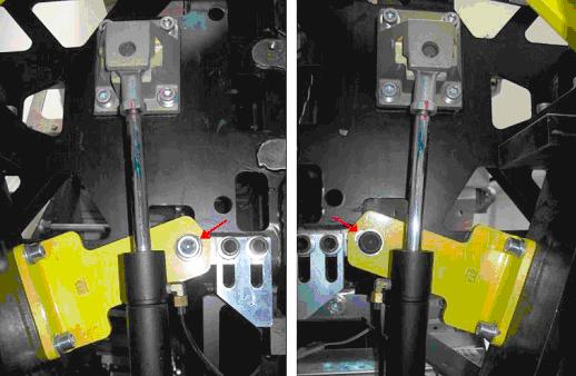
- Using a 14mm Hex wrench and appropriate extensions barely loosen the 16mm bolt on the Tilt bracket on each side of the gantry. Loosen them just enough to allow the Rotating Frame to move or tilt back slightly within the range of the bolt hole. You want a sufficient amount of friction between the bolt and bracket so they slide back and forth in the bolt hole. Refer to illustration X:
Figure 12. Slightly Loosen Bolt
- Rock the Rotating Frame back and forth. Engage the Tilt Direction Switch (S10) FORWARD for 5-6 seconds or until the rotating frame stops. The bracket should be tight against the 16mm bolt.note:
You will hear the air bleeding out for the short period S10 is engaged during the first few iterations.
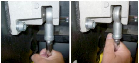
- Check the tension on each actuator rod by twisting them by hand. If there is too much air in the system they will twist easily by hand. They will get harder to twist as the hydraulic pressure in the system increases.
Figure 13. Check Actuator Rod Tension
- Engage the Tilt Direction Switch (S10) BACKWARD 5-6 seconds or until the rotating frame stops. The bracket should be tight against the 16mm bolt.
- Check for improved hydraulic pressure by twisting the actuator rods by hand on each side.
- Engage the Tilt Direction Switch (S10) FORWARD 5-6 seconds or until the rotating frame stops. The bracket should be tight against the 16mm bolt.
- Check for improved hydraulic pressure by twisting the actuator rods by hand on each side.
- Repeat this process at least 10 times. The actuator rods will become very difficult to twist by hand.
- Engage the Tilt Direction Switch (S10) BACKWARD approximately 2 seconds or until the 16mm bolt is centered in the bolt hole on the Tilt bracket. This indicates that sufficient pressure is present to hold the rotating frame in place when the Tilt brackets are removed.
- Using the appropriate extensions and hex wrench to provide safe clearance between rotating and stationary frames, remove the 16mm Tilt Bracket bolt from the left side of the gantry as viewed from the back of the gantry.note:
In this next step expect the rotating Frame to move back slightly.
- Using the appropriate extensions and hex wrench to provide safe clearance between rotating and stationary frames, remove the 16mm Tilt Bracket bolt from the right side of the gantry as viewed from the back of the gantry.
- Once the Rotating Frame is free use the Tilt Direction Switch (S10) to “Jog” the Rotating Frame a few degrees in both directions to ensure there is sufficient hydraulic pressure in the system to control the tilt function.
- Remove the remaining bolts from the Tilt brackets and remove them completely from the gantry.
- Turn on the Console using the power switch under the console table top. The system software should automatically boot the system up to full operation.
- Have one FE stand at the side of the gantry and observe the hydraulic lines.note:
When moving the gantry tilt for the first time periodically stop titling the gantry and check the gantry movement for obstructions and slack in the hydraulic lines.
- Set the Service Switch (S4) to “Normal” position.
- Place the Tilt Enable Switch (S9) to “OFF” position.
- Stand at the side of the gantry (clear of tilt motion) and use one of the operators control panels on the front of the gantry to tilt the gantry forward using the tilt feature to tilt the gantry to the -20 degree position for the first time and stop.
- Check the hydraulic lines to ensure that there is enough slack to accommodate further tilting.
- Stand at the side of the gantry (clear of tilt motion) and use one of the operators control panels on the front of the gantry to tilt the gantry forward using the tilt feature to tilt the gantry to the -10 degree position for first time and stop.
- Check the hydraulic lines on both sides to ensure that there is enough slack to accommodate further tilting.note:
It may be possible for the gantry to move erratically when it passes through the zero degree (fully upright) position the first time and its weight becomes supported by the new hydraulic system.
- While staying clear of the gantry (stand at its side), use one of the operators control panels on the front of the gantry to continue tilting the gantry forward to the zero degree (fully upright) position and stop.
- Check the hydraulic lines to ensure that there is enough slack to accommodate further tilting.
- While staying clear of the gantry (stand at its side), use one of the operators control panels on the front of the gantry to continue tilting the gantry forward to the + 10 degree position and stop. Be prepared for possible erratic tilt motion during this step.
- At the + 10 degree position check the hydraulic lines for proper slack and gantry in general for any other obstructions.
- While staying clear of the gantry (stand at its side), use one of the operators control panels on the front of the gantry to continue tilting the gantry forward to the +30 degree position where it should come to a complete stop.
- At this time tighten up the tie wraps by hand holding the hydraulic lines.
- Tilt the gantry back to the zero degree (fully upright) position and stop.
- Continue with Section 5 FINALIZATION.
4 Finalization
Procedure
- Install the 2 rear cover lower cantrell brackets (bottom latches) previously removed.
- When the tilt pump is warm to the touch, make final speed adjustments. Refer to Hydraulic Tilt Motor Speed Adjustment.
- Reassemble gantry by replacing any covers removed. Remember to remove power prior to replacing covers and restore power when done.
- Refer to “Clean-up and Personal Hygiene,” located in Equipment Service - Chemicals and Materials, for proper disposal of contaminated materials.
- Perform a system test using the System Scanning Test found in the Functional Checks folder.