- Topic ID: id_15460361
- Version: 2.0
- Date: Nov 8, 2018 1:36:53 AM
Hydraulic Tilt Motor Speed Adjustment
Prerequisites
Overview
This procedure defines the method for testing and adjusting gantry tilt speed.
Procedure
- Remove the gantry right side cover
- Disable Axial drive from the service switch board for safety.
- Remove gantry rear base covers.
- Set the Tilt switch (S4) to service mode on the service switch
board. With this switch in service mode the gantry control panel LED
display will show tilt speed (degrees per second) during tilt motion.

- notice
note:Tilt speed will vary based upon hydraulic fluid temperature. Adjustments should be made at normal scan room temperature settings.
- From zero (0) degrees tilt, press and hold the tilt forward
button,
 . Observe tilt speed on the LED display
above the tilt buttons.
. Observe tilt speed on the LED display
above the tilt buttons.Specification for tilt motion is 0.8 to 1.2 degrees per second as shown by the gantry control panel display.
- Press and hold backward tilt button,
 . Observe tilt speed
on the LED display above the tilt buttons.
. Observe tilt speed
on the LED display above the tilt buttons.Specification for tilt motion is 0.8 to 1.2 degrees per second as shown by the gantry control panel display.
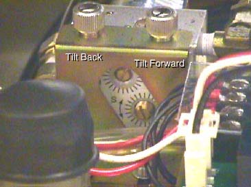
- If necessary, adjust speed control valve for one (1) degree
per second motion for forward or back. See Figure 1. Pay attention to the direction for slower and faster as indicated
on the scale for each adjustment.
Figure 1. Tilt Speed Adjustment Screws
- Repeat until tilt speed for both directions is within specifications.
- Now tilt the gantry forward to S30. Observe the S25 to S30 speed.
If a noticeable difference is observed, then check the hydraulic fluid
levels.note:
This is a self bleeding system. Trapped air can cause slowed or limited tilt range. Exercising the full range of motion several times should purge any trapped air from the hydraulic system. Tilt Back. Tilt Forward. Tilt Forward. Tilt Back
- Restore gantry to normal operation.
- Re-install gantry base covers.
- Set the tilt service switch S4 back to normal position
- Enable Axial drive.
- Install gantry right side cover.
Finalization
- Verify full range of tilt operation.