- Topic ID: id_15460547
- Version: 2.0
- Date: Nov 8, 2018 1:37:58 AM
HP Z400 Lower Level FRU Replacement
Prerequisites
Overview
This procedure describes and illustrates the steps necessary to replace lower level FRUs in the HP Z400 Host PC as applicable with the Lightspeed 7X systems.
Lower Level FRUs Supported:
-
SCSI Controller Card
-
Future FRUs
Swapping internal components between the same type HP computer (example Z400 > Z400) is allowed. Swapping components between a HP different type HP Computers (example: xw8400 > Z400) is not allowed.
1 Powering Off (Shutting Down) the Operator Console
Procedure
- Select one of the following methods to Power Off the Operator
Console:
-
If Applications are running, click Shut Down on the desktop and select the Shutdown option.
-
If Applications are down, open a Unix Shell using the Toolchest and type: {ctuser@hostname} haltENTER
The Operator Console monitor will display a “System Halted” message when it is acceptable to power off the Operator Console.
-
- Power OFF the Operator Console at the front panel switch.
- Make sure to follow all Lockout/Tagout requirements while performing this procedure. Refer to Equipment Service - Lockout-Tagout-PPE procedure. For added protection, disconnect the Twist-N-Lock Main Power Cable from rear of console.
2 Removing the HP Z400 Host Computer from Operator Console
Procedure
- Remove the front and rear Operator Console covers.
- Remove the cable connections to the HP Z400 Host Computer chassis.note:
Verify that all cables are labeled and clearly marked. If necessary, add a label for clarity.
- Remove the power cord at the rear of the Host Computer chassis.
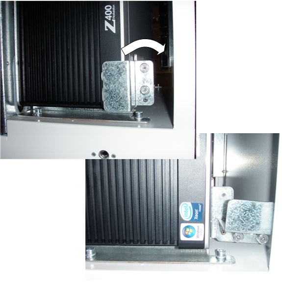
- Loosen the two (2) cap screws on the retaining bracket at the lower right front of the Host Computer chassis, which holds the Host Computer in place in the Operator Console right side compartment. See Figure 1
- Pivot the Retaining Bracket away from the Host Computer chassis.
Figure 1. HP Z400 Console Mounting
- Slide the Host Computer forward (out the front of console) and set aside.
3 Access Panel Removal
Procedure
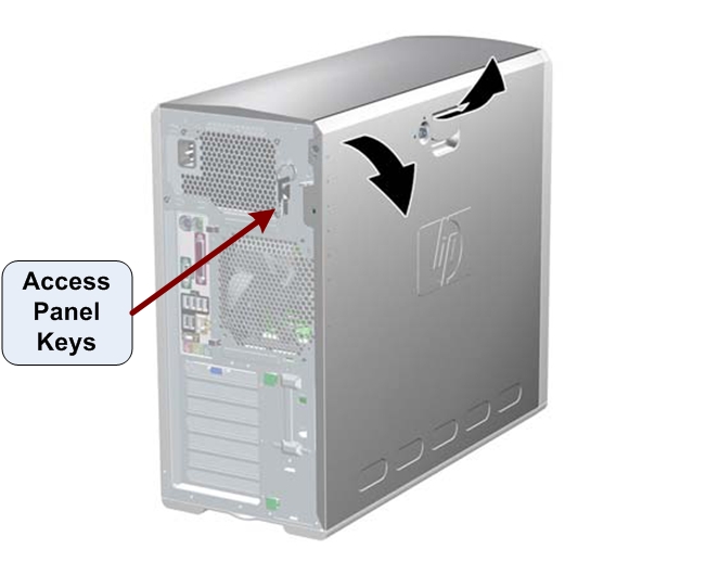
- If necessary, unlock the access panel using the keys located in the rear of the workstation. (See Figure 2
- Once unlocked, pull up on the handle and lift off the access
panel cover.
Figure 2. Access Panel Cover Removal
4 Replacing HP Z400 Host Computer Lower Level FRUs
4.1 SCSI Card Replacement
Procedure
- Follow the steps in HP Z400 SCSI Card Replacement for replacing the (Optional) SCSI Card in the HP Z400 Host Computer.
- Return to this procedure when finished and continue with Section 4.5.
4.2 Future FRU's
Procedure
- Reserved for future FRU additions
- Return to this procedure when finished and continue with Section 4.5.
5 Reinstalling the HP Z400 Host Computer in Operator Console
Procedure
- Slide the HP Z400 Host Computer into the Operator Console from the front.
- Hand tighten the two (2) cap screws on the retaining bracket to secure the Host Computer chassis to the Operator Console right side compartment.
- Mount the power cord to the rear of the Host Computer chassis.
- Replace the rear cable connections.
Figure 3. HP Z400 Cable Connections

6 Powering-On the Operator Console
Procedure
- Reconnect the Twist-N-Lock Main Power Cable from rear of console and remove Lockout Tagout protection applied earlier.
- Power ON the Operator Console at the console’s front panel switch.
- Visually verify that the Host Computer front panel Power LED is illuminated. If not, press the Host Computer front panel power switch to apply power to the Host Computer.
7 Finalization
Procedure
- Refer to System Scanning Tests in the Functional Checks chapter of this manual to confirm proper operation.
- Check that all customer functions are operational. (Auto voice, filming, network, archive).
- Reinstall Console Front and Rear Covers.