- Topic ID: id_15460360
- Version: 2.0
- Date: Nov 8, 2018 1:38:38 AM
Gantry Tilt/Fan Relay (GTFR) Board Replacement
Prerequisites
Overview
Procedure
- If possible, Tilt gantry back 20 degrees to aid in this procedure.
- Remove gantry right side cover.
Refer to
- notice
- Turn off the three (3) main power switches (Axial Drive, HVDC, 120VAC) on the Service Switch Panel.
- Remove gantry base covers on the left side (TGPU side of gantry)
- notice
- Remove the nuts that fasten the plastic cover to the GTFR Board.
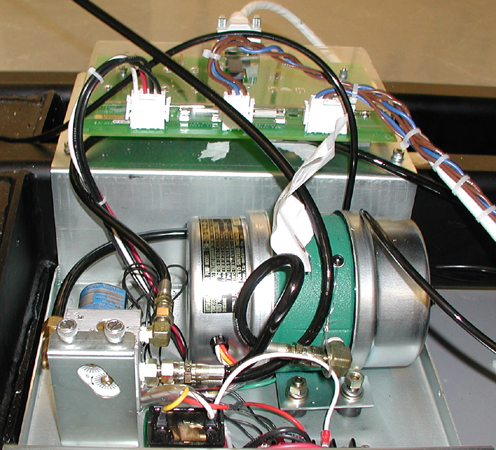
Figure 1. GTFR Board
- Disconnect the cable connections from the board.
- Remove the stand-offs that held the cover to remove the GTFR board.
- Install new GTFR board.
- Place new GTFR board in the same location as the original.
- Install stand-offs and GTFR board cover.
- Install cable connections.
- Re-install the gantry base covers previously removed.
- Restore power to the gantry from the service switch panel (AC Power, HVDC, Axial Drive enable and table drives reset).
- Install the gantry right side cover.
 |
|
Finalization
- Perform a Tilt Functional Test by using the Hydraulic Tilt Motor Speed Adjustment procedure.