- Topic ID: id_15460518
- Version: 2.0
- Date: Nov 8, 2018 1:38:02 AM
Gantry Balance Sensor Hardware Replacement
Prerequisites
Overview
This procedure defines the steps necessary to replace the gantry balance sensor hardware.
1 Gantry Setup for replacement
Procedure
- Drive the table to its full back position and position it full up if not already there.
- Remove gantry right side cover.
Refer to
- Turn off 120 VAC, Axial Drive and HVDC Service Switches.
- Remove the Gantry left side, top, rear and front covers. The front cover can stay connected to the gantry cables, just needs to be moved away from the gantry toward the table. Connect the rear cover E-stop cable to the terminator on the gantry.
- Set up Field ESD strap connecting it to a gantry ground point. Wear the strap when replacing any of the gantry balance circuit boards in the following sections.
2 Part replacement
Perform the section below for the part you are replacing. This covers 3 parts, Sensor buffer board, and each of the two balance sensors.
2.1 Sensor buffer board
Procedure
- Remove the two cables from the buffer board.
Figure 1. Sensor buffer board
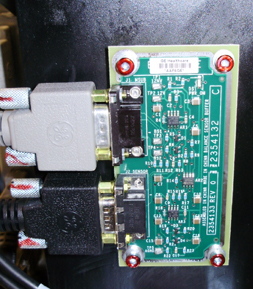
- Remove the 4 M4 screws (3 mm hex wrench) and replace the board.
- After installing new board, torque the 4 M4 screws to:
- Reattach the cables.
2.2 Front balance sensor (front side of gantry leg)
Procedure
- Remove the 2 M4 screws on the cover (3 mm hex wrench). If gantry
cabling is in the way, cut cable ties as necessary to gain access.
Figure 2. Sensor board
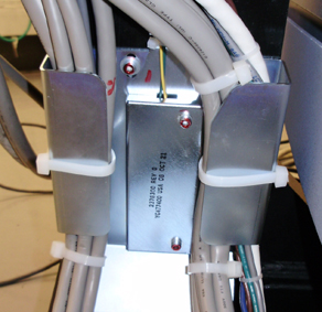
- Remove the 4 M4 Screws holding the sensor board to the gantry leg (3 mm hex wrench).
- Replace board and torque the 4 M4 screws to:note:
The sensor material is quite brittle. Make sure the sensor is placed flat on the gantry leg and without any obstructions before tightening the screws.
- Replace cover making sure the wires are in the cutout and not pinched by the cover. Torque M4 screws to the settings in the step above.
- Reinstall any removed cable ties for the gantry harness.
2.3 Side balance sensor (between gantry leg and tilting assembly)
Procedure
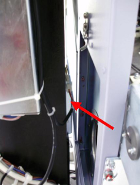
- The gantry side sensor is located on the side of the gantry
leg as shown below. The heater filter is removed for clearer view.
Figure 3. Side Sensor
- Remove the Gantry heater assembly using the Gantry Heater Replacement procedure and remove the filter as well. This is necessary to gain access for tightening the screws that restrain the new sensor board.
- Tilt the gantry forward to about 20 degrees as shown on the
gantry display for easy access to the side sensor board through the
heater port using the following steps.
-
Turn on the gantry 120VAC service switch and press the table drives enable at the lower right corner of the service switch panel.
-
Turn on service mode switch S4 (up position)
-
Turn on the tilt enable switch S9 (on position)
-
Use the tilt switch S10 to tilt the gantry forward. Look to see that you have access to the sensor board through the blower/filter port.
-
Turn off the gantry 120VAC service switch.
-
- Using the access through the heater/filter port, disconnect the molex connector for the sensor board.
- Remove the 2 M4 screws holding the cover on the gantry leg.
- Remove the 4 M4 Screws holding the sensor board to the gantry leg (3 mm hex wrench).
- Replace board and torque the 4 M4 screws to:note:
The sensor material is quite brittle. Make sure the sensor is placed flat on the gantry leg and without any obstructions before tightening the screws.
- Replace cover making sure the wires are in the cutout and not pinched by the cover. Torque M4 screws to the settings in the step above.
- Reconnect the molex connector to the sensor.
- Turn on the gantry 120VAC service switch and press the table drives enable at the lower right corner of the service switch panel.
- Return the gantry to a zero tilt position using switch S10. Then turn Tilt Enable S9 to Off and put the Service Mode switch in the down position.
- Turn the 120 VAC service switch off.
- Reinstall the gantry heater assembly using the Gantry Heater Replacement procedure. Do not power on the gantry.
3 Sensitivity matrix
Procedure
- At the console, go to the Service Desktop and select Shell from the Utilities tab.
- Type the following command line to remove the current sensitivity
matrix and exit the shell.
rm /usr/g/fw/sensmatrix.dat
exit
4 Finalization
Procedure
- Perform Gantry Service balance from the Common Service Desktop Calibrations Tab. This procedure will have you install the gantry balance trial weights to create a new sensitivity matrix. Reference the Gantry Balance Procedure if needed.
- Reinstall gantry front, rear, top and left side covers.
Refer to
- Turn on the gantry 120 VAC, HVDC and Axial drive service switches.
- Install the gantry right side cover.
- Run the System scanning test from the Functional Checks procedure list.