- Topic ID: id_15460499
- Version: 3.0
- Date: Jun 15, 2020 11:01:35 PM
Gantry Heater Replacement
Prerequisites
Overview
This procedure defines the steps necessary to replace the gantry heater/blower assembly.
Procedure
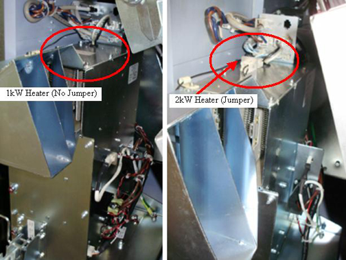
- For reference when ordering the heater assembly reference Figure 1. Note the 2 kW heater has a jumper on top and the
wiring on the right side is significantly reduced.
Figure 1. 1 kW and 2 kW Heater identification
- Move table to its lowest elevation.
- Remove gantry right side cover.
Refer to
- Turn OFF the Axial Drive and HVDC switches on the gantry’s Service Switch Panel.
- Rotate the gantry by hand to gain clear access to the heater assembly. Position the tube at approximately 9 o'clock which will have the weight stack above the detector at the 3 o'clock position behind the service switch panel.
- Turn OFF the 120 VAC switch on the gantry’s Service Switch Panel.
 danger
- Perform all required LOTO activities to remove all power to the gantry.
- Remove the gantry left side cover, top covers and front cover.
- Remove the gantry tilting assembly bottom cover.
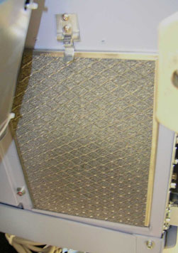
- The heater has an air intake filter on the left side. See Figure 2.
Figure 2. Air Intake Filter
- Remove the 3 screws in the front by the latch using a 5 mm hex
wrench. See Figure 3.
Figure 3. Heater Screws
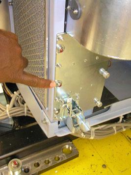
Figure 4. Gantry Heater Mounting Screws
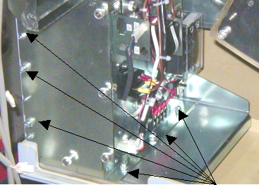
- Remove the 3 screws on the inside plate that holds the heater to the plate using a 5 mm hex wrench.
- Slide the heater forward and carefully remove all connecting cables.
- Carefully remove the heater assembly from the gantry.
- Install the new heater assembly by reversing the above steps. Install all hardware and cables.
- Torque the Heater assembly mounting screws to:
- Install the gantry tilting assembly base cover.
- Install the gantry front cover, top covers and left side cover.
Refer to
- Remove LOTO and restore power to system.
- Enable 120 VAC HVDC and Axial Drive service switches from the service switch panel. Press the table drives enable button on the lower right corner of the service switch panel.
- Install the gantry right side cover.
Finalization
- Perform a System Scanning Test from the Functional Checks menu of the service manual to ensure system operation.