- Topic ID: id_15460299
- Version: 3.0
- Date: Apr 27, 2020 2:58:49 AM
GSI Meter Verification
Prerequisites
Overview
This document provides the necessary steps to verify the Generator internal kV and mA metering circuitry calibration for Gemstone Spectral Imaging [GSI] scanning mode.
1 Gantry Preparation
Procedure
- Move table to longitudinal home position.
- Remove gantry right side cover.
- Turn off AXIAL DRIVE ENABLE switches on Service Switch panel.
- Rotate gantry such that High Voltage Tank assembly is in 3 o'clock position.
- Engage rotational lock.
2 Oscilloscope Preparation
Procedure
- Plug oscilloscope into one of the gantry's service outlets.
- Disconnect all probes from oscilloscope.
- Turn on oscilloscope and warm up for a minimum of 20 minutes.
- Perform oscilloscope Signal Path Compensation.note: The menu selections are based on a TDS3034B oscilloscope and might be different on similar oscilloscopes.
- Press UTILITY.
- Select CAL from SYSTEM.
- Press SIGNAL PATH PASS.
- Press OK COMPENSATE SIGNAL PATHS.note: “Calibration in progress, please wait.” is displayed during compensation.note: Compensation can take up to 10 minutes.note: When completed, “Signal path compensation has successfully completed. Push MENU OFF to remove this message” is displayed.
- Press MENU OFF.
- Connect 10X probe to oscilloscope Channel 1 plug.
- Perform oscilloscope Probe Compensation:
- Attach probe tip and reference lead to PROBE COMP connectors.
- Press AUTOSET.
- Check shape of displayed waveform for a flat top square wave.note: If waveform is not a flat top square wave, adjust probe Low Frequency Compensation and repeat (a) - (c).
3 Internal kV
Procedure
- Complete Gantry and Oscilloscope Preparation steps (See Sections 4.1 and 4.2).
- Insert RED lead banana plug into High Voltage Tank BLUE receptacle
(Item 1 in Figure 1) and connect
oscilloscope 10X Probe Signal to RED lead clip.
Figure 1. High Voltage Tank Meter Receptacles
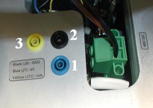
- Insert BLACK lead banana plug to High Voltage Tank BLACK receptacle (Item 2 in Figure 1) and oscilloscope 10X Probe Common to BLACK lead clip.
- Configure oscilloscope.note: The menu selections are based on a TDS3034B oscilloscope and might be different on similar oscilloscopes.
- Set HorizontalSCALE to 400ms.
- Press CH 1.
- Set VerticalSCALE to 2 V / division.
- Set VerticalPOSITION to 2 minor ticks (0.4 of a division) from top of screen.
- Press TriggerMENU, SOURCE, CH. 1.
- Press TriggerMENU, COUPLING, DC.
- Press TriggerMENU, SLOPE, NEG.
- Set TriggerMENU, LEVEL to –3.00V.
- Press TriggerMENU, MODE & HOLD, NORMAL.
- Set HorizontalDELAY to OFF state.note: This sets Horizontal Trigger to 10%.
- Press MEASURE, GATING, BETWEEN V BAR CURSORS.
- Press MEASURE, SELECT MEASUREMENT FOR CH. 1, MEAN.
- Press MENU OFF.note: Pulse mean is displayed on right hand side of screen.
- Perform Oscilloscope Offset Value.note: This is oscilloscope-offset value that will be subtracted from true measurement values in later steps.note: Do NOT change the vertical scale on oscilloscope after measuring offset value.
- Press TriggerFORCE TRIG.
- Record oscilloscope Channel 1 mean value in volts.
- Select DIAGNOSTICS from Service Desktop.
- Select KV & MA (X-RAY).
- Select GSI Protocol #1 from X-ray Test Type pulldown menu.note: In Gantry Params pane, Gantry parameter should be set to DISABLED.
- Click RUN.
- Press START on SCIM when it flashes.
- On oscilloscope, use SELECT - COARSE knob to place left cursor to just inside of waveform front edge.
- Press SELECT and use SELECT - COARSE knob to place right cursor to just inside of waveform back edge.
- Record Channel 1 Mean value in volts, including minus sign if there is one.
- Obtain Measured kV value by (-20kV/V) * (Channel 1 Mean value - Oscilloscope Offset value).
- Verify that Measured kV is between 92.7kV
and 113.3kVnote: If the condition fails, perform Filament Calibration and retest. If the condition fails on first retest, replace High Voltage Tank and retest. If the condition fails on second retest, replace Tube and retest.
- Record results in appropriate GE e4879 Installation form, GE e4879 Certified Component Verification form, or GE Data Report Planned Maintenance Schedule form.
- On oscilloscope, set HorizontalSCALE to 200ms.
- From KV & MA (X-RAY) window, Select GSI Protocol #2 from X-ray Test Type pulldown menu.
- Repeat steps 10 - 17.
- On oscilloscope, set HorizontalSCALE to 100ms.
- From KV & MA (X-RAY) window, Select GSI Protocol #3 from X-ray Test Type pulldown menu.
- Repeat steps 10 - 17.
4 Internal mA
Procedure
- Complete Gantry and Oscilloscope Preparation steps (See Sections 4.1 and 4.2).
- Insert RED lead banana plug into High Voltage Tank YELLOW receptacle (Item 3 in Figure 1) and connect oscilloscope 10X Probe Signal to RED lead clip.
- Insert BLACK lead banana plug to High Voltage Tank BLACK receptacle (Item 2 in Figure 1) and oscilloscope 10X Probe Common to BLACK lead clip.
- Configure oscilloscope.note: The menu selections are based on a TDS3034B oscilloscope and might be different on similar oscilloscopes.
- Set HorizontalSCALE to 400ms.
- Press CH 1.
- Set VerticalSCALE to 2 V / division.
- Set VerticalPOSITION to 2 minor ticks (0.4 of a division) from top of screen.
- Press TriggerMENU, SOURCE, CH. 1.
- Press TriggerMENU, COUPLING, DC.
- Press TriggerMENU, SLOPE, NEG.
- Set TriggerMENU, LEVEL to –3.00V.
- Press TriggerMENU, MODE & HOLD, NORMAL.
- Set HorizontalDELAY to OFF state.note: This sets Horizontal Trigger to 10%.
- Press MEASURE, GATING, BETWEEN V BAR CURSORS.
- Press MEASURE, SELECT MEASUREMENT FOR CH. 1, MEAN.
- Press MENU OFF.note: Pulse mean is displayed on right hand side of screen.
- Perform Oscilloscope Offset Value.note: This is oscilloscope-offset value that will be subtracted from true measurement values in later steps.note: Do NOT change the vertical scale on oscilloscope after measuring offset value.
- Press TriggerFORCE TRIG.
- Record oscilloscope Channel 1 mean value in volts.
- Select DIAGNOSTICS from Service Desktop.
- Select KV & MA (X-RAY).
- Select GSI Protocol #1 from X-ray Test Type pulldown menu.note: In Gantry Params pane, Gantry parameter should be set to DISABLED.
- Click RUN.
- Press START on SCIM when it flashes.
- On oscilloscope, use SELECT - COARSE knob to place left cursor to just inside of waveform front edge.
- Press SELECT and use SELECT - COARSE knob to place right cursor to just inside of waveform back edge.
- Record Channel 1 Mean value in volts, including minus sign if there is one.
- Obtain Measured mA value by (-100kV/V) * (Channel 1 Mean value - Oscilloscope Offset value).
- Verify that Measured mA is between 480mA
and 720mAnote: If the condition fails, perform Filament Calibration and retest. If the condition fails on first retest, replace High Voltage Tank and retest. If the condition fails on second retest, replace Tube and retest.
- Record results in appropriate GE e4879 Installation form, GE e4879 Certified Component Verification form, or GE Data Report Planned Maintenance Schedule form.
- On oscilloscope, set HorizontalSCALE to 200ms.
- From KV & MA (X-RAY) window, Select GSI Protocol #2 from X-ray Test Type pulldown menu.
- Repeat steps 10 - 17.
- On oscilloscope, set HorizontalSCALE to 100ms.
- From KV & MA (X-RAY) window, Select GSI Protocol #3 from X-ray Test Type pulldown menu.
- Repeat steps 10 - 17.
5 Finalization
Procedure
- Turn off and unplug oscilloscope.
- Disconnect oscilloscope probe from High Voltage Tank metering
connections.
- Disconnect oscilloscope 10X Probe Signal and Common from leads.
- Unplug leads from High Voltage Tank receptacles.
- Turn on AXIAL DRIVE ENABLE switches on Service Switch Panel.
- Install gantry right side cover.
- Prepare oscilloscope for storage.
- Store data form with system history records.