- Topic ID: id_15460266
- Version: 2.0
- Date: Nov 8, 2018 1:37:50 AM
GOC6.6 VCT Host Computer (Z820/Z840) Replacement
Prerequisites
Overview
This procedure shall be followed when replacing the Z820/Z840 computer in the GOC6.6 VCT console.
1 Console Computer Removal
Procedure
- Select one of the following methods to Power OFF the Console:
- If Applications are up, click on the Shut Down button on desktop display and select Shutdown.
- If Applications are down, open a Terminal Window. Type: halt , then press Enter.
- When halt command has finished, power Off the console at the front panel switch.
- Apply LOTO for Console. For procedures, see Equipment Service - Lockout-Tagout-PPE.
- Remove the Console’s Keyboard Tabletop assembly and Front
and Rear console chassis covers.
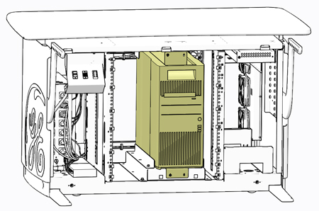
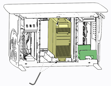
Refer to .
Figure 1. Z820/Z840 Computer in GOC6.6 Chassis
- At the rear of the Z820/Z840 computer chassis, disconnect all
cables attached to the computer. Make certain that all cables are
properly labeled.
Figure 2. Rear View of Console Chassis
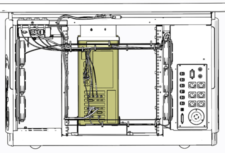
Figure 3. Z820 Computer Connections
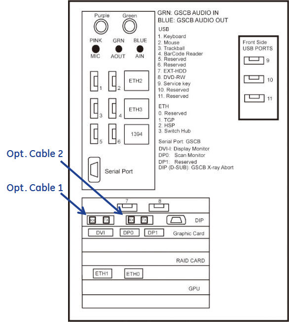
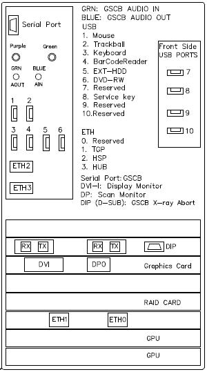
Figure 4. Z840 Computer Connections
- Remove the four (4) 3mm socket caps mounting screws holding
the computer in console chassis.
Figure 5. Z820/Z840 Mounting Screws
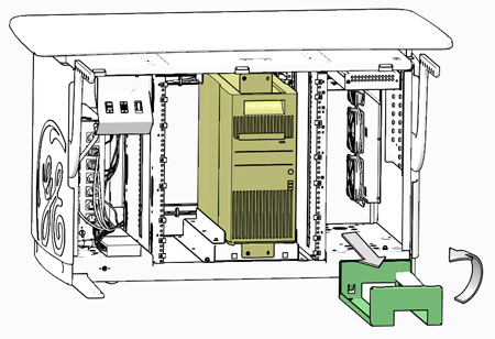
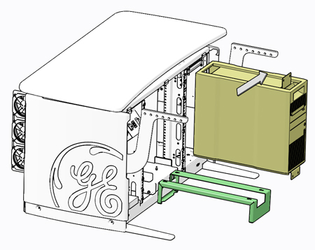
- Locate the Computer Service Platform stored in the right side
of the console chassis. Remove Computer Service Platform from its
storage location and place the place it in front of the computer.
Figure 6. Computer Service Platform
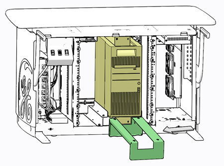
- Using the tabs on the Computer Service Platform, engage the
platform to the console chassis to hold the platform in place.
Figure 7. Computer Service Platform Placement
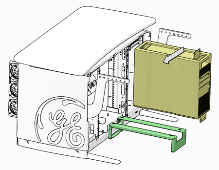
- Slide the computer forward onto the platform using the handle
on the top front of the computer.
Figure 8. Computer Removal onto Service Platform

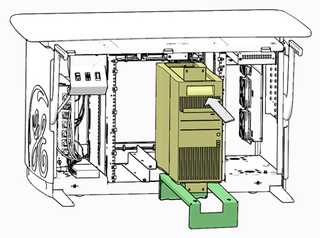
- With the computer fully extracted and placed on the platform,
lift the computer up and away using the two handles on the top of
the computer.
Figure 9. Computer Fully Extracted
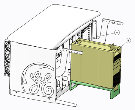
Figure 10. Computer Removal
2 Replacement Z820/Z840 Computer Preparation
Procedure
- Transfer the computer chassis mounting brackets to new computer if necessary.
- In order to maintain existing Software Option Licenses on the
system, the Ethernet NIC Card from the original the Computer must
be exchanged with the replacement computer. If one is certain that
the original Ethernet NIC Card has not failed, swap this card to the
replacement computer to avoid acquiring new Software Option Licenses.
Follow NIC Card Replacement procedure for swapping the Ethernet NIC Card.
3 Z820/Z840 Computer Install
Procedure
- Place the replacement computer onto the Computer Service Platform.
Figure 11. Computer Install onto Service Platform
 note:
note:Transfer the computer mounting brackets to new computer if necessary.
- Fully slide the replacement computer back into the console chassis,
until mounting brackets are flush against the chassis.
Figure 12. Computer Install into Console Chassis
- Remove and store the Service Platform.
- Install and torque the four (4) 3mm socket cap screws removed
earlier.note:
Torque each the for (4) 3mm socket cap mounting screws to:
- Reconnect all cables removed earlier to the computer (reference Figure 3).
- Remove LOTO on console. For procedures, see Equipment Service - Lockout-Tagout-PPE.
4 Functional Checks, Alignments and Setups
Procedure
- Power On console and check that the computer is not flashing or sounding any POST errors. If POST errors are present, reference the Computer Troubleshooting procedure.
- Insert OS disk in computer DVD drive, Power Off the computer, and disconnect the Hospital Network connection.
- Perform a Load From Cold. Reference (13HW31.x) Load From Cold (NIO64) or (16HW36.x) Load From Cold (GOC6.6 Z840) procedure
for instructions.
5 Finalization
Procedure
- Install console covers and Keyboard Tabletop assembly. Refer to .
- Perform the instructions from the procedure list.
- Perform the instructions from the procedure list.
- Perform the instructions from the procedure list for each software version (13HW31.x for NIO64 / 16HW36.x for GOC6.6 Z840).