- Topic ID: id_15460684
- Version: 3.0
- Date: Jun 15, 2020 11:00:52 PM
GOC6.5 Host Computer Replacement
Prerequisites
Overview
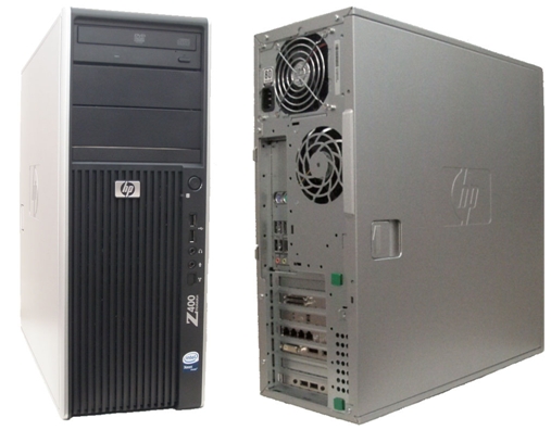
This procedure describes and illustrates the steps necessary to replace the Host Computer.
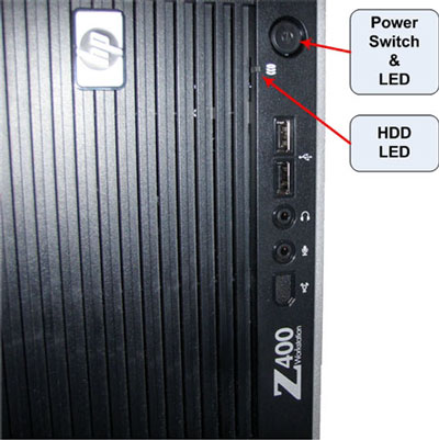
Figure 1. GOC6.5 Host Computer (HP Z400)
1 Power-Off (Shut Down) the Console
Procedure
- Select one of the following methods to power off the Operator
Console:
-
If applications are running, click the Shut Down icon and select Shut Down.
-
If applications are down, open a Unix Shell using the Toolchest. Type: {ctuser@hostname} halt. Press Enter.
The Operator Console monitor will display a ‘System Halted’ message when it is acceptable to power off the Operator Console.
-
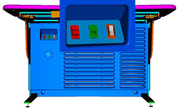
- Power OFF the Operator Console at the front panel switch (Figure 2).
Figure 2. Console Power Switch
- Perform the prescribed Lockout/Tagout procedure. For added protection, disconnect the Twist-N-Lock Main Power Cable from rear of console.
2 Remove the Old Host Computer
Procedure
- Remove the Front and Rear Operator Console Covers per the prescribed cover removal procedure..
- Remove the cable connections to the Host Computer chassis being
replaced.note: Verify that all cables are labeled and clearly marked. If necessary, add a label for clarity.
- Remove the power cord at the rear of the Host Computer chassis
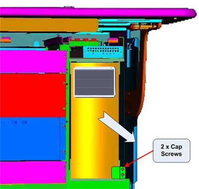
- Loosen the two (2) cap screws (Figure 3) on the retaining
bracket at the lower right front of the Host Computer chassis, which
holds the Host Computer in place in the Operator Console right side
compartment.
Figure 3. Host Computer Mounting
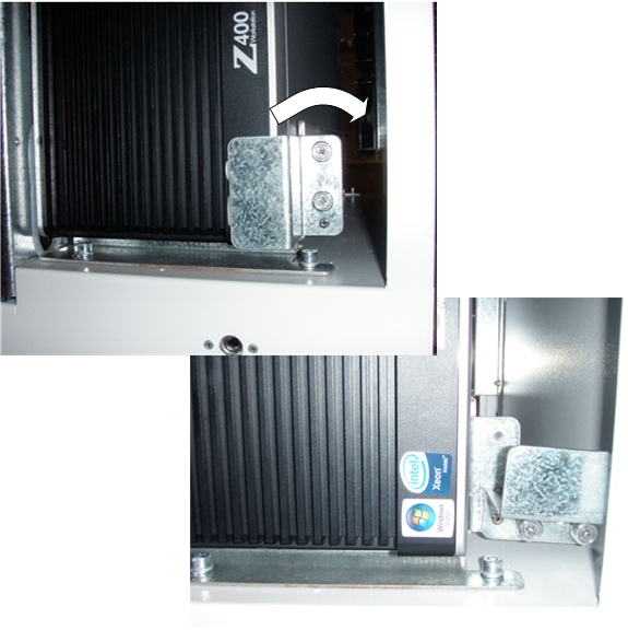
- Pivot the Retaining Bracket away from the Host Computer chassis.
See Figure 4
Figure 4. Host Computer Retaining Bracket
- Slide the Host Computer chassis forward (out the front of console)
and set aside.note:
It will be necessary to push the Host Computer from the rear of the console. Push the Host Computer out far enough to allow for hand gripping of the chassis, since there are no handles on the Z400 Host Computer. From the front of the console, pull the Host Computer the rest of the way out.
The Host Computer is held in place by close tolerances of the mounting brackets. The Host Computer fits tightly in its brackets.
3 Exchange NIC Card (eth0-3) Host Computer
Procedure
- Follow the Host Computer NIC Exchange
- HP Z400 procedure. Then return to these instructions.note: The System Option Licenses are tied to Host Computer’s Ethernet (eth0) MAC address. The NIC card can be exchanged if one is reasonably certain that the Host Computer failure is not related to the NIC card. This will allow for the reuse of System Option Licenses, otherwise new Licenses must be obtained.
4 Install the Replacement Host Computer
Procedure
- Slide the replacement Host Computer into the Operator Console
from the front.note: The Host Computer is held in place by close tolerances of the mounting brackets. The Host Computer fits tightly in its brackets. Slide the Host Computer fully into the console until it come in contact with the bracket stops at the rear of the lower mounting bracket. Pivot the retaining bracket back into place.
- Hand tighten the two (2) cap screws on the retaining bracket to secure the Host Computer chassis to the Operator Console right side compartment.
- Mount the power cord to the rear of the Host Computer chassis.
- Replace the rear cable connections.
Figure 5. HP Z400 Host Computer Connections

- For cabling details, refer to the appropriate interconnect located in the System Diagrams folder of this service methods publication.
5 Power-On the Operator Console
Procedure
- Reconnect the Twist-N-Lock Main Power Cable from rear of console and remove Lockout Tagout protection applied earlier.
- Power ON the Operator Console at the console’s front panel switch.
- Visually verify the Host Computer front panel Power LED is illuminated.
If not, press the Host Computer’s front panel power switch to
apply power to the Host Computer.
Figure 6. HP Z400 Host Computer Power Switch
6 Verify Replacement Host Computer Operation
Procedure
- Verify that the Host Computer has powered up and is not displaying
or sounding any POST Errors.note: See Host Computer Troubleshooting if any errors appear.
- In order to assure proper operation of the Host computer it is necessary to perform software Load from Cold (LFC). Refer to the Software Chapter of this manual for software loading procedures.
- After completing the software LFC, make certain that you perform a final Save System State.
7 Finalization
Procedure
- After completing the LFC procedure, perform a complete shutdown of the Operator Console and restart the system.
- Refer to System Scanning Tests in the Functional Checks chapter of this manual to confirm proper operation.
- Reinstall Console Front and Rear Covers.