- Topic ID: id_15460683
- Version: 3.0
- Date: Jun 15, 2020 11:01:06 PM
DIG DIP Card Replacement
Prerequisites
Overview
This procedure describes and illustrates the steps necessary to replace the Data Acquisition & Image Generation (DIG) Computer DIP Card.
This procedure covers both the HDIP and the VDIP cards used in the High Definition and VCT systems HDIG and VDIG Computers respectively.
Figure 1. VDIP (VCT)
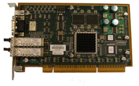
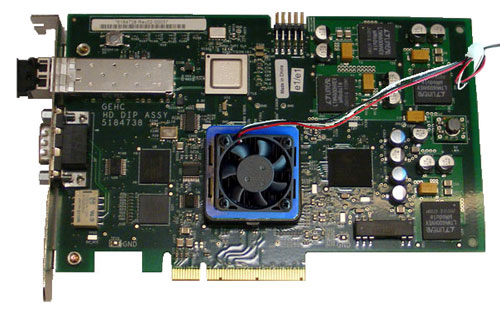
Figure 2. HDIP (HD)
1 Power-Off (Shut Down) the Console
Procedure
- Select one of the following methods to power off the Operator
Console:
-
If applications are running, click the Shut Down icon and select Shut Down.
-
If applications are down, open a Unix Shell using the Toolchest. Type: {ctuser@hostname} halt. Press Enter.
The Operator Console monitor will display a ‘System Halted’ message when it is acceptable to power off the Operator Console.
-
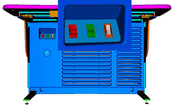
- Power OFF the Operator Console at the front panel switch. (See
Illustration 2.)
Figure 3. Console Power Switch
- Perform prescribed Lockout/Tagout procedure. For added protection, disconnect the Twist-N-Lock Main Power Cable from rear of console.
2 Remove DIG Computer
Procedure
- Remove the front and rear Operator Console Covers per prescribed cover removal procedure.
- Remove the cable connections at the rear of the DIG Computer
chassis.note:
Verify that all cables are labeled and clearly marked. If necessary, add a label for clarity.
- Remove the power cord at the rear of the DIG Computer chassis.
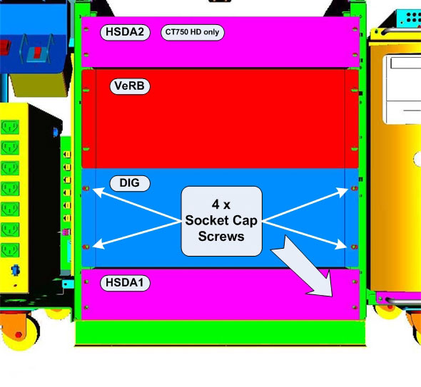
- Remove the four (4) 5mm socket cap screws and washers from the
front of the DIG Computer chassis, holding the chassis to the Operator
Console rack.
Figure 4. DIG Computer Mounting
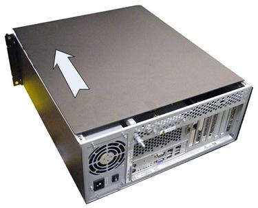
- Slide the DIG Computer chassis forward (out the front of console) and set aside. See the Safety, Equipment Service - Console chapter of the service manual for additional information regarding Console Component Lifting .
3 Remove HDIP or VDIP Card from DIG Computer
Procedure
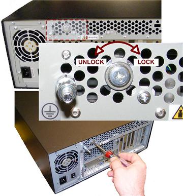
- At the rear of the DIG Computer Chassis, release the Chassis
Cover Lock using a Phillips screwdriver. Back out lock screw at least
two (2) full turns.
Figure 5. DIG Computer Chassis Cover Lock
- Slide the Chassis Cover towards the front of the chassis and
remove.note:
You may need to tap on back upper edge of cover to release cover before sliding forward.
Figure 6. DIG Computer Cover Removal
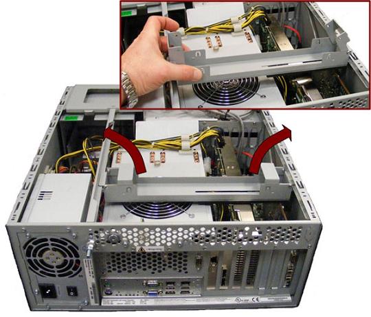
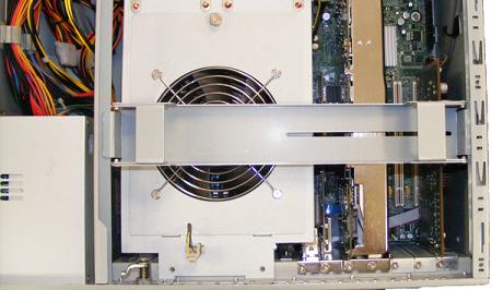
- Remove the Expansion Card Hold-down Clamp from DIG Computer
Chassis.
Figure 7. DIG Computer Expansion Card Hold-down Clamp Removal
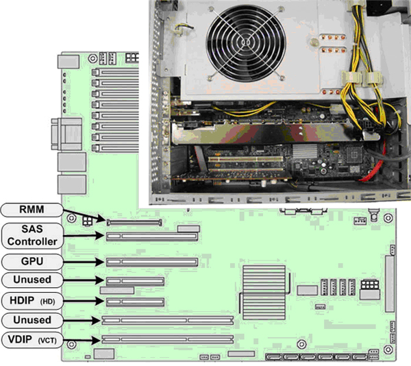
- Remove the Phillips Screw holding the HDIP or VDIP Card in the
DIG Computer chassis and carefully remove the card from the Systemboard.
Figure 8. DIG Computer HDIP or VDIP Card Locations
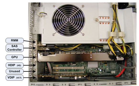 note:
note:Illustration shows DIG Computer with VDIP installed. DIG Computer on HD will have a HDIP Card instead.
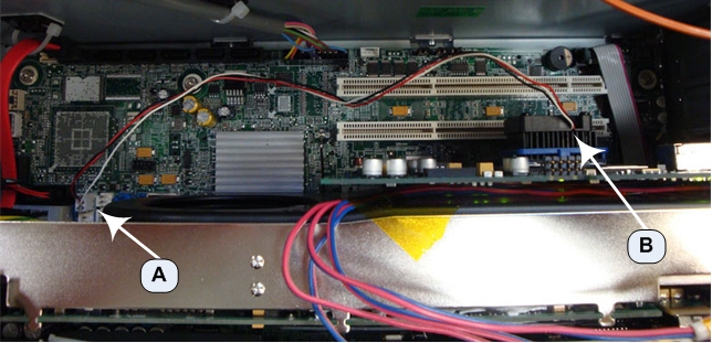
HDIP Card also has a Cooling Fan power connection on the HDIG Systemboard that will need to be unplugged when the HDIP is removed. See Figure 9.Figure 9. HDIP Heatsink Fan Power Connection
4 Install Replacement HDIP or VDIP Card in DIG Computer
Procedure
- Carefully install the replacement HDIP or VDIP Card in the same
location (slot) in the DIG Computer. Make sure all cables are clear
of the HDIP or VDIP Card and the card seats firmly in the Systemboard.
Figure 10. DIG Computer HDIP or VDIP Card Slot Locations
- Reinstall the Phillips Screws to secure the HDIP or VDIP Card
to the chassis.note:
In the case of a HDIP Card replacement, make sure to also connect the HDIP Heat Sink Fan Power Cord to the Systemboard's Fan Power Connection.
- Reinstall the Expansion Card Hold-down Clamp in the DIG Computer
Chassis .
Figure 11. DIG Computer Expansion Card Hold-down Clamp Placement
 note:
note:The Expansion Card Hold-down Clamp must be installed as illustrated above. The Clamp should be centered over the Cooling Fan with slotted end over expansion cards.
- Reinstall the DIG Computer Chassis Cover and lock the cover in place.
5 Re-Install DIG Computer
IMPORTANT: IN ORDER TO MEET EMC REQUIREMENTS, THE CHASSIS COVERS MUST BE PROPERLY INSTALLED AFTER SERVICING. CHECK THAT THE COVERS ARE MOUNTED FIRMLY IN PLACE AND LOCKED DOWN WHERE APPLICABLE.
Procedure
- Slide the replacement DIG Computer into the Operator Console from the front.
- Replace the four (4) 5mm socket cap screws and washers to secure the DIG Computer chassis to the Operator Console rack. Torque to 4.6 N-m.
- Mount the power cord to the rear of the DIG Computer chassis and verify that its power supply switch is turned to the ON position.
- Replace the rear cable connection(s).
Figure 12. HDIG Cable Connections and Destination
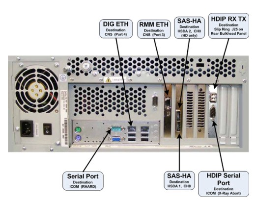
Figure 13. VDIG Cable Connections and Destination
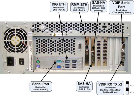
For cabling details, refer to the appropriate interconnect located in the System Diagrams folder of this service methods publication.
6 Power-On the Operator Console
Procedure
- Reconnect the Twist-N-Lock Main Power Cable from rear of console and remove Lockout Tagout protection applied earlier.
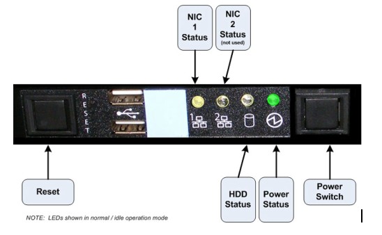
- Power ON the Operator Console at the console’s front panel switch.
- Visually verify the DIG Computer front panel Power LED is illuminated.
If not, press the DIG front panel power switch to apply power to the
DIG Computer.
Figure 14. DIG Front Panel Indicators and Switches
7 Verify Replacement DIG Computer HDIP or VDIP Card Operation
Procedure
- Verify that the DIG Computer has powered up and is not displaying
or sounding any POST Errors.note:
See DIG Troubleshooting if any errors appear.
- No other verifications steps required.
8 Finalization
Procedure
- Refer to System Scanning Test to confirm proper operation.
- Reinstall Console Front and Rear Covers.