- Topic ID: id_15460243
- Version: 3.0
- Date: Jun 15, 2020 11:00:50 PM
DIG 1 or 2 Replacement with DIG-VeRB Common Computer
Prerequisites
Overview
This procedure describes steps necessary to replace the DIG 1 or 2 with a DIG-VeRB Common Computer that does not contain the DIP and SAS cards. The DIP and SAS Cards will be removed from the existing Chassis and installed in the replacement DIG.
DO NOT REMOVE THE GPU FROM THE COMMON COMPUTER FRU
Definitions:
VeRB1 = Volume Reconstruction Box, the 1 means it has the Nvidia GPU
VeRB2 = Volume Reconstruction Box, the 2 means it has the AMD / ATI GPU
SAS = Serial Attached SCSI
DIP = DAS Interface Processor, either VDIP or HDIP
GPU = Graphics Processing Unit
BMC = Baseboard Management Controller (Hardware on the Mother board)
RMM = Remote Management Module ( Adapter Card )
IPMI = Intelligent Platform Management Interface ( BMC is IPMI compatible )
Ipmitool = Utility for controlling IPMI enabled devices
SNMP = Simple Network Management Protocol
PXE Boot = Preboot eXecution Environment (pronounced pixie) boots/retrieves OS & Application software over a network.
IP Addressing:
172.16.0.2 darc = DIG
172.16.0.5 verb = VeRB
172.16.0.3 darcrmm = DIG rmm
172.16.0.4 verbrmm = VeRB rmm
172.16.0.6 darcarray = darcarray
172.16.0.7 darcarray2 = darcarray2
172.16.0.10 darcbmc = darcbmc
172.16.0.11 verbbmc = verbbmc
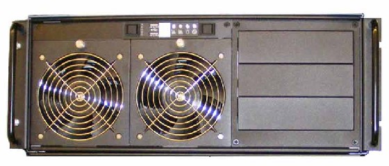
Figure 1. Data Acquisition & Image Generation Computer (DIG)
1 Power-Off (Shut Down) the Console
Procedure
- Perform the following methods to power off the Operator Console:
-
If applications are running, click the Shut Down icon and select Shut Down.
-
If applications are down, open a Unix Shell using the Toolchest.
-
Type: {ctuser@hostname} halt. Press Enter.
The Operator Console monitor will display a System Halted message when it is acceptable to power off the Operator Console.
-
- Power OFF the Operator Console at the front panel switch. Perform prescribed Lockout/Tagout procedure. For added protection, disconnect the Twist-N-Lock Main Power Cable from the rear of the console.
2 Remove DIG Computer
Procedure
- Remove the front and rear Operator Console Covers per prescribed cover removal procedure.
- Remove the cable connections at the rear of the DIG Computer
chassis being replaced.note:
Verify that all cables are labeled and clearly marked. If necessary, add a label for clarity
- Remove the power cord at the rear of the DIG Computer chassis.
- Remove the four (4) 5mm socket cap screws and washers from the front of the DIG Computer chassis, holding the chassis to the Operator Console rack.
- Slide the DIG Computer chassis forward (out the front of console) and set aside.
3 Cover Removal
Procedure
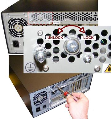
- At the rear of the DIG2 Computer Chassis, release the Chassis
Cover Lock using a Phillips screwdriver. Back out lock screw at least
two (2) full turns.
Figure 2. DIG Computer Chassis Cover Lock
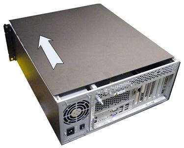
- Slide the Chassis Cover towards the front of the chassis and
remove.note:
You may need to tap on back upper edge of cover to release cover before sliding forward.
Figure 3. DIG Computer Cover Removal
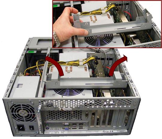
- Remove the Expansion Card Hold-down Clamp from DIG2 Computer
Chassis.
Figure 4. DIG2 Computer Expansion Card Hold-down Clamp Removal
- Remove the Phillips Screw holding the VDIP or HDIP Card in the
DIG2 Computer chassis and carefully remove the card from the System
board.
Figure 5. VDIG-1&2 Computer VDIP Card Locations
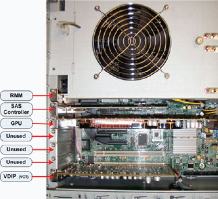
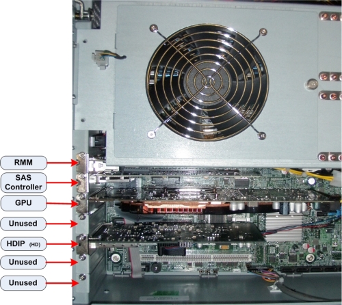
Figure 6. HDIG-1&2 Computer HDIP Card Locations
4 Remove DIP card and SAS Board from the defective DIG
Procedure
- Remove DIP Card from the slot shown above.
- Remove SAS Card from the slot shown above.
5 Install DIP card and SAS Board on Replacement DIG
Procedure
- Install DIP Card into the slot shown above. See Figure 7 on fan power cable connection on HDIP cards
- Install SAS Card into the slot shown above.
- Reinstall the Expansion Card Hold-down Clamp in the DIG Computer
Chassis.
Figure 7. HDIP fan power cable connection
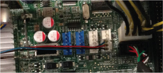
Figure 8. DIG-1or DIG-2 Computer Expansion Card Hold-down Clamp Replacement
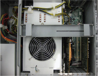 note:
note:The Expansion Card Hold-down Clamp must be installed as Figure 8. The Clamp should not cover the Cooling Fan with slotted end over expansion cards.
- Reinstall the DIG Computer Chassis Cover and lock the cover in place.
6 Install Replacement DIG Computer
Procedure
- Slide the replacement DIG Computer into the Operator Console from the front.
- Replace the four (4) 5mm socket cap screws and washers to secure the DIG Computer chassis to the Operator Console rack. Torque to 4.6 N-m.
- Mount the power cord to the rear of the DIG Computer chassis and verify that its power supply switch is turned to the ON position.
- Replace the rear cable connection(s).
Figure 9. VDIG Cable Connections & Destination
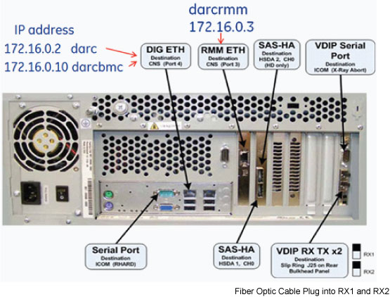
Figure 10. HDIG Cable Connections & Destination
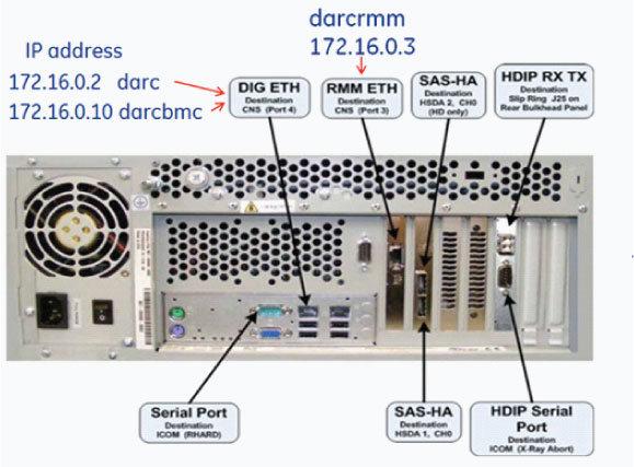
For cabling details, refer to the appropriate interconnect located in the System Diagrams folder of this service methods publication.
7 Power-On the Operator Console
Procedure
- Reconnect the Twist-N-Lock Main Power Cable from rear of console and remove Lockout Tagout protection applied earlier.
- Power ON the Operator Console at the console front panel switch.
- Do not allow Applications to start. During boot-up, cancel
Application Startup when the CT Software Auto-start pop-up window appears.
Note: Do not allow Applications to start. During boot-up If you miss the 5 seconds to stop application type the following:
slay -f startMon
8 Verify Replacement DIG Computer Operation
Procedure
- Verify that the DIG Computer has powered up and is not displaying
or sounding any POST Errors.note:
See DIG Troubleshooting procedure in the service manual if any errors appear.
- Run reconfig
- Open a Terminal window and log on as Root.
- Type: reconfigEnter
- Config
- Select Acceptnote:
No changes are required in the System, Preferences, Hardware, Network settings. The procedure just needs to be executed in order for the automated scripts to run. During the reconfiguration process the DHCP Server running on the Host Computer is reconfigured to support the new DIG Computer Ethernet MAC addresses.
note:Until the System Configuration procedure is performed, the Linux OS bootup text will display an error message when the DIG computer attempts to mount its NFS on the Host Computer. Ignore the error message.
note:This could take up to 10 minutes waiting for the darc to boot up, please be patient.
- If you receive the “DIG is not booting” rerun reconfig – you do not have to reboot the console.
- Do you wish to reboot Now ? YES Reboot for change to take effect –minutes
- Open a Unix Shell
Note: applications do not autostart after a reconfig
- Type: st to bring application up
9 Finalization
Procedure
- Perform a complete shutdown of the Operator Console and restart the system.
- Confirm VeRB or DIG communication
- In Terminal Window, Type: ping verb and ping darc , reboot could take up to 10 minutes.
- In Terminal Window, Type: ping verbrmm and ping darcrmm
- If these computers fail to respond to the ping command, check Network Switch and Cables. Otherwise suspect a failed computer. See DIG/VeRB Troubleshooting in the Troubleshooting Chapter in the Service Manual
- Run a patient scan to confirm proper system operation.
Select Image Quality tab -> QA Phantom ImgSer Or
Select Manufacturing tab -> Service System Scanning Test-> lower all ma settings to 40 ma
- Reinstall Console Front and Rear Covers.