- Topic ID: id_15460414
- Version: 3.0
- Date: Jun 15, 2020 11:00:44 PM
Console Power Switch or Cable Replacement
Prerequisites
Overview
This procedure describes and illustrates the steps necessary to replace a Console Power Switch or Power Switch Cable in the upper left compartment of the Operator Console.
This procedure requires disassembly of part of the console chassis. Allow ample time and work space to perform this procedure.
1 Power-Off (Shut Down) the Console
Procedure
- Select one of the following methods to power off the Operator
Console:
-
If applications are running, click the Shut Down icon and select Shut Down.
-
If applications are down, open a Unix Shell using the Toolchest.
Type: {ctuser@hostname} haltEnter.
The Operator Console monitor will display a ‘System Halted’ message when it is acceptable to power off the Operator Console.
-
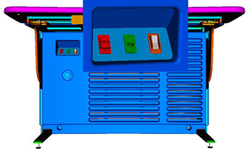
- Power OFF the Operator Console at the front panel switch. (See Figure 1.)
Figure 1. Console Power Switch
- Perform prescribed Lockout/Tagout procedure. For added protection, disconnect the Twist-N-Lock Main Power Cable from the rear of the console.
2 Remove Console Power Switch Panel Assembly from Chassis
Procedure
- Remove the front and rear Operator Console Covers per prescribed cover removal procedure.
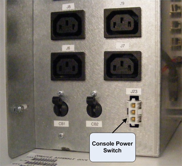
- Disconnect Console Power Switch cable from the Power Distribution
Box, Connector J23.
Figure 2. Console Power Switch Cable Connection at Power Distribution Box
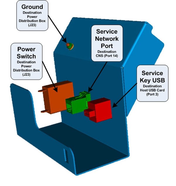
- Disconnect the Ethernet Port and USB cables from the rear of
the Console Power Switch Panel Assembly (Figure 3).
Figure 3. Console Power Switch Panel Assembly Connections
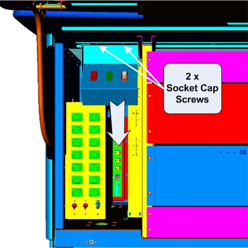
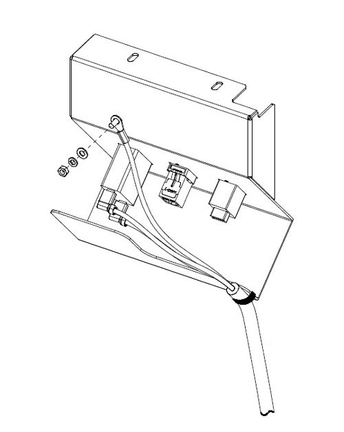
- Loosen and remove the two (2) 4mm socket cap mounting screws
holding the console Power Switch Assembly to the console chassis and
remove the entire Console Power Switch Assembly with its wiring harness
from console.
Figure 4. Console Power Switch Panel Assembly Removal
With the Power Switch Panel Assembly removed from the console chassis, either the Power Switch or the Power Switch Cable can be easily access and replaced.
3 Install Replacement Console Power Switch
Procedure
- 1. Disconnect the two (2) Fast ON Connectors on the rear
of the Power Switch.
Figure 5. Console Power Switch Cable Connections
- Remove Failed Power Switch by compressing the spring clips on the backside and pressing the Switch out the front of the Power Switch Panel.
- Install the replacement Power Switch by pressing the switch into the Power Switch Panel from the front.
- Reconnect the two (2) Fast On Connectors removed earlier.
4 Install Replacement Console Power Switch Cable
Procedure
- Disconnect the two (2) Fast ON Connectors on the rear of the Power Switch.
- Disconnect the Power Switch Panel Ground wire by loosing the Hex Nut and removing the Ground Wire ring lug from the ground stud. (See Figure 5.)
- Cut any Ty-Raps® holding the cable to the Power Switch Panel Assembly.
- Install the replacement Power Switch Cable by reconnecting the two (2) Fast On Connectors to the Power Switch. Refasten the Ground Wire to the Ground Stud on the Power Switch Panel Assembly using the hex nut removed earlier. Torque to 1.3 N-m.
- Replace any Ty-Raps® removed earlier.
5 Reinstall Console Power Switch Assembly on Chassis
Procedure
- Place and hold the repaired Console Power Switch Panel Assembly in upper left compartment of console.
- Install the Power Switch Panel Assembly using the two (2) 4mm socket cap mounting screws removed earlier. Torque to 2.9 N-m.
- Replace the Ethernet and USB cables back in the rear of the Console Power Switch Panel Assembly.
- Reconnect Console Power Switch Cable to the Power Distribution Box, Connector J23.
- Check that the two (2) Circuit Breakers (CB1 & 2) on the Power Distribution Box are set ON.
6 Power-On the Operator Console
Procedure
- Reconnect the Twist-N-Lock Main Power Cable from rear of console and remove Lockout Tagout protection applied earlier.
- Power ON the Operator Console at the console’s front panel switch.
7 Verify Replacement Power Switch and/or Cable Operation
Procedure
- Verify that power is restored to all the console components:
- Internal Computer modules (i.e. Host, DIG, HSDA ... etc.)
- External Peripherals (i.e. Monitors, Peripheral Tower ... etc)
See Power Distribution Box Troubleshooting if any problems are suspected.
- Remove console power.
8 Finalization
Procedure
- Install console Front Cover.
- Restore console power.