- Topic ID: id_15460688
- Version: 2.0
- Date: Nov 8, 2018 1:37:27 AM
Power Distribution Box Troubleshooting
1 Overview
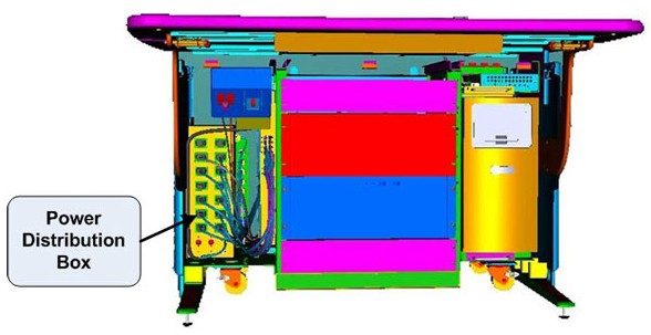
The follow information will assist in confirming if the Operator Console is experiencing a power distribution hardware fault. The following checks should be sufficient in determining if the Power Distribution Box located inside the Operator Console (Figure 1) is suffering from hardware issues at the prescribe Field Replaceable Unit (FRU) level.
Figure 1. Power Distribution Box Location
|

2 Console Power Distribution Troubleshooting
2.1 General Troubleshoot Checklist
Before proceeding with the rest of this Troubleshooting Guide, use the following checklist to find possible solutions for general power up problems.
-
Is the System receiving power?
-
Is the Main System Disconnect enabled (i.e. A1 Panel or similar)?
-
Is the PDU power up?
-
Is the UPS operational (if equipped)?
-
-
Is the Console receiving power?
-
Has Circuit Breaker #7 (CB7) tripped on PDU?
-
Are the correct phases connected to the Operator Console at the PDU?
-
Is the Twist-N-Lock Power Cord securely fastened to the Operators Console Bulkhead Panel?
-
2.2 Power Distribution Box Troubleshoot Checklist
-
Are the Console Components receiving power?
-
Is the console power switch on and functioning?
-
Is the console Power Switch Assembly plugged into J23 on the Power Distribution Box?
-
Has Circuit Breaker #2 (CB2) tripped on Power Distribution Box?
note:This Circuit Breaker also protects the Power-On Contactor Coil inside the Power Distribution Box. Only the two Accessory Outlets will remain on if CB2 trips.
See Operator Console Circuit Breaker Table 1 below for more details.
-
-
Are only some of the Console Components receiving power?
-
Has Circuit Breaker #1 Tripped?
- Suspect power problems related to Recon Engine Computers (i.e. DIG, HSDA(s) or VeRB (if equipped).
- Possible failure of internal components of the Power Distribution Box (i.e. Line Filter).
-
Has Circuit Breaker #2 Tripped?
- Suspect power problems related to Host Computers (i.e. Host PC, Peripheral Tower(s) or Monitors.
- Possible failure of Power-On Contactor Coil or other internal components of the Power Distribution Box (i.e. Line Filter).
-
Has Circuit Breaker #3 Tripped?
- Suspect power problems related to Accessory plugged into these outlets.
-
-
Disconnect loads (power cords) from Power Distribution Box and reset Circuit Breaker(s).
-
Are Circuit Breaker(s) still tripping?
Yes
- Suspect component failure internal to Power Distribution Box.
- Replace Power Distribution Box (FRU).
-
Are Circuit Breaker(s) still tripping?
No
- Reconnect power cords in a systematic method to determine which console component is over loading the Circuit Breaker(s).
-
3 Console Power Distribution
The Power Distribution Box (or Outlet Box) in the left compartment of the Operator Console is responsible for distributing AC Power to the components in the GOC6 Console. Incoming power from the Power Distribution Unit (PDU) of the CT System is two (2) phase 208 Vac. This incoming 2 phase AC power is routed through Line Filters and Circuit Breakers and then sent to numerous IEC power outlets in a load balanced manner.
It is important that the console components be connected to specific power outlets on the Power Distribution Box to maintain proper power load balance. If components are not connected to their proper power outlets, a possible imbalance in power distribution may cause circuit breakers to trip when the console is powered on.
It is important to understand that the only method to completely remove power from the console is with the removal of the Twist-N-Lock Power Connector on the rear Console Bulkhead Panel. The Circuit Breakers on the Power Distribution Box and the Console Power Switch only switch different circuits in and out of the energized state. Power is still present in the Power Distribution Box with the Circuit Breakers and Console Power Switch turned off!
3.1 Console Power Distribution Schematic
The incoming two (2) phase 208 Vac power is split inside the Power Distribution Box into two (2) primary single phase 120Vac circuits. These circuits eventually supply 120 Vac power to all the computers and other components inside the operator console. For cabling details, refer to the appropriate interconnect located in the System Diagrams folder of this service methods publication.
The Operator Console Power Switch energizes a three (3) Pole Contactor inside the Power Distribution Box, allowing 120 Vac power to be distributed through line filters and then onto the console components.
3.2 Console Power Distribution Circuit Breakers
Primary electrical protection for the entire Operator Console is located on the Power Distribution Unit (PDU), Circuit Breaker #7 (CB7). All Circuit Breakers located at the Operator Console are for protecting specific subsections of the power distribution at the console.
3.3 Console Power Distribution Box Connections and Circuit Breaker Locations
Figure 2. Power Distribution Box Connections and Circuit Breaker Locations: Internal to Operator Console
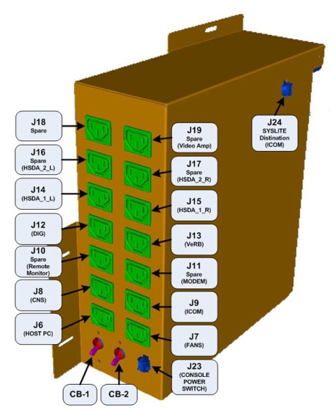
Figure 3. Power Distribution Box Connections and Circuit Breaker Locations: External to Operator Console
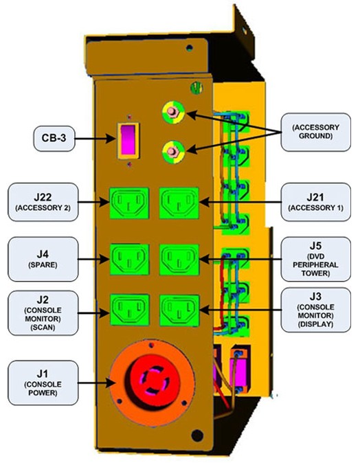
 |
|