- Topic ID: id_15460441
- Version: 3.0
- Date: Sep 29, 2020 10:20:18 PM
Belt Removal and Installation
Prerequisites
Overview
This procedure defines the steps necessary to replace the gantry drive belt.
1 Gantry Preparation
Procedure
- Move table to the home position.
- Remove gantry right side cover.
Refer to
- Turn OFF the Axial Drive and HVDC switches on the gantry’s Service Switch Panel.
- Rotate the gantry to place the tube at the 10 o'clock position for access to encoder. Do not engage the rotational lock.
- Turn OFF the 120 VAC switch on the gantry’s Service Switch Panel.
 danger
- Remove power from the Gantry using LOTO procedures.
- Remove the gantry left side cover, top covers and front and
rear covers. Also remove the back screws of gantry tilting bottom
cover to allow easier access to belt pulley cover screws.
Refer to
- notice
- Remove the upper slip ring cover by loosening the captive screws and then remove the lower slip ring cover sliding the lower cover around the slip ring on the TGPU side of the gantry so it can be easily pulled away from the gantry on the upper side of the slip ring. The lower slip ring can not be easily remove if left in the lower location as the gantry bottom tilting cover is too close to the slip ring.
- Remove the Home Flag assembly to prevent damage.
Refer to Home Flag Sensor Board Assembly Replacement procedure.
- Remove the Axial Encoder to prevent damage to the encoder gear
teeth.
Refer to Axial Encoder Assembly Replacement.
 |
2 Drive Belt Removal
Procedure
- warning
- Using the 5 mm hex key remove the three (3) screws that secure
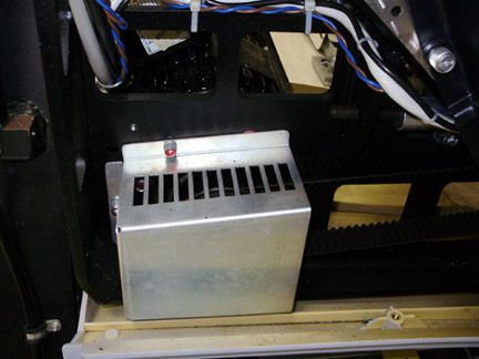
the Drive Gear Cover, and remove the Cover.
Figure 1. Drive gear cover
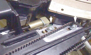
- To release tension on the belt pulley, loosen the two (2) M12
screws with the 10mm hex head socket, then Using the 6 mm hex head
socket and the 12 inch extension, fully loosen the elongated hex screw
to loosen the drive belt from the drive gear. Reference Figure 2.
Figure 2. Belt pulley
- Remove the drive belt from the drive gear.
- Work the belt toward the table on the rotating assembly. Keep all slack at the tube side of the gantry.
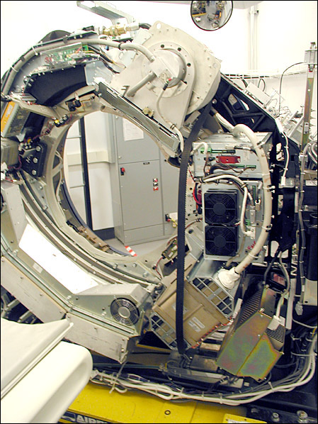
- Work the belt through the large gap to the right of the Tube,
around the inverter and to the DAS (see Figure 3).note:
Your gantry may look different from the following illustrations. Process is the same.
Figure 3. Axial Drive Belt Installation/Removal Example
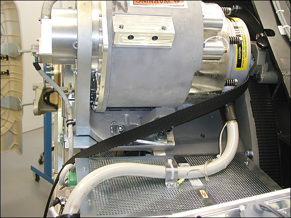
- At this point the Belt slackens. Carefully work the belt around
the rest of the rotating gantry, completing the removal process.
Figure 4. Belt Path Around Tube
 |
3 Drive Belt Installation
Procedure
- Install the Belt using the removal steps in reverse order.
- Install the Home Flag assembly and Axial Encoder per Home Flag Sensor Board Assembly Replacement and Axial Encoder Assembly Replacement procedures.
- Slide the Belt over the main Drive Gear and align it towards the back of the rotating assembly teeth. Check both top and bottom.
- Work the belt through the pulley tensioner assembly and place on motor drive gear.
- Tighten the elongated hex screw using a 6 mm hex head socket and a 12 inch extension. Apply enough tension so the washer can be rotated with your fingers.
- Rotate the Gantry by hand and recheck tension of washer. Make sure the belt does not slip off tensioning pulley and is tracking correctly toward the rear of the gantry.
- Perform the CT belt tension check and adjustment procedure but not the finalization section.
- Install the drive gear cover.
4 Gantry Reassembly
Procedure
- Install the slip ring bottom safety cover using the captive fasteners on the cover. Tighten the screws for the tilting assembly bottom cover if previously loosened when removing slip ring cover.
- Remove LOTO and restore power to the system.
- Enable 120 VAC HVDC and Axial Drive service switches from the service switch panel. Press the table drives enable button on the lower right corner of the service switch panel.
- Ensure that the Home Flag Assembly (refer to Home Flag Sensor Board Assembly Replacement) and the Axial Encoder Assembly (Refer to Axial Encoder Assembly Replacement) have been installed and are functioning correctly.
- Turn OFF the Axial Drive, HVDC and 120 VAC switches on the gantry’s Service Switch Panel.
- Install the gantry front, rear, top and left side covers.
Refer to
- Enable 120 VAC HVDC and Axial Drive service switches from the service switch panel. Press the table drives enable button on the lower right corner of the service switch panel.
- Install the gantry right side cover.
5 Finalization
Procedure
- Perform a Fastcal from the Daily Prep button of the scan display.
- Perform a System Scanning Test from the Functional Checks menu of the service manual to ensure system operation.