- Topic ID: id_15460412
- Version: 4.0
- Date: Apr 22, 2019 12:56:53 AM
CT Belt Tension Check & Adjustment
Prerequisites
Overview
During deceleration from .35s, above-grade installations are seeing high gantry vibrations. Engineering testing shows that belt tension has a significant impact on rotation deceleration vibration. Increasing belt tension decreases vibration by approximately 40%. The desired outcome of this procedure is to achieve an average reading at all 4 locations between 85 and 120 on the Gates Sonic meter or equivalent device.
1 Sonic Meter Preparation
Procedure
- Turn the Tension meter on.
- For the Gates Sonic Tension Meter model 507 C, press the Measure button and then press the Hz button. The green LED will be flashing. For an equivalent meter, make sure it is set p to measure frequency.
2 Sonic meter Setup Test
Procedure
- Position the Tube at 0 degrees while rotating by hand in
the CW direction.note:
Always rotate the gantry in the CW direction when checking the tension of the belt. Rotating the gantry CW and then CCW will relieve the belt tension and give inaccurate measurements.
- From the Slip Ring side of the gantry hold the tension meter
sensor half way between the motor pulley and idler pulley (upper side
of belt) approximately 1/2 of an inch (1.5cm) from the top of the
belt.note:
The closer the meters sensor is to the belt without touching, the better the reading will be.
- Using your finger, pluck the belt or tap the belt lightly between
the motor pulley and the idler pulley to make it vibrate. A waveform
graphic will show up on the LCD screen. After the signal is processed
properly, the belt frequency will appear on the screen and a successful
measurement on the Gates meter will beep 3 times, and the green LED
turns on steady to indicate a successful reading.note:
This is a technique that may take some practice at first.
The gantry belt tension has to be done at 4 different locations, as this is the most accurate (i.e., Tube at 0, 90, 180, 270 degrees).
3 Adjusting Belt Tension
Procedure
- Rotate gantry clockwise 2 turns to even out the belt tension.
- Rotate the gantry so the tube is at the 12 O'clock (0 degree) position.
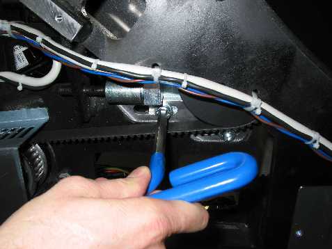
- To unlock the tensioner assembly, loosen the two M12 screws
one turn using a 10mm hex key. See Figure 1.
Figure 1. Unlocking Tensioner Assembly
- From the Slip Ring side of the gantry hold the tension meter
sensor half way between the motor pulley and idler pulley (upper side
of belt) approximately 1/2 of an inch (1.5cm) from the top of the
belt.note:
The closer the meters sensor is to the belt without touching, the better the reading will be.
- Using your finger, pluck the belt or tap the belt lightly between the motor pulley and the idler pulley to make it vibrate. A waveform graphic will show up on the LCD screen. After the signal is processed properly, the belt frequency will appear on the screen and a successful measurement on the Gates meter will beep 3 times, and the green LED turns on steady to indicate a successful reading.
- Write down the value acquired, (You will be averaging 4 readings at 0, 90, 180 and 270 degree gantry positions).
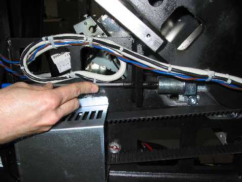
- To adjust the belt, tighten the elongated hex screw using a
6mm hex key and a 12 inch ( 30.5cm) extension. Turn wrench in 1/4
turn increments. (Clockwise tightens the belt, counter-clockwise loosens
the belt.) and repeat step 5 until you achieve a value in the range
defined. See Figure 2.
Figure 2. Tightening Elongated Hex Screw
- Tighten the two M12 screws to 66 N*m (50 FT*lb) to lock the tensioner assembly.
- Rotate the gantry to the next position (90 degrees).
- Once again, loosen the two M12 screws to unlock the tensioner assembly.
- Repeat the process as described in steps 5 through 7 for the 90, 180 and 270 degree locations achieving an average reading at all 4 locations between 85 and 120.
 warning
- When you have a good average reading at all 4 positions, Tighten the two M12 screws to 66 N*m (50 FT*lb) to lock the tensioner assembly.
A passing reading is in the range of 85 to 102.
 |
4 Finalization
Procedure
- Run the gantry with motor power at .35 seconds for a couple of minutes
- Repeat steps 5 to ensure that ther belt is still within the 85 to 102 range, if not repeat this adjustment procedure until the belt frequency is within this range.