- Topic ID: id_15460707
- Version: 2.0
- Date: Nov 8, 2018 1:38:04 AM
Axial Drive Module Replacement
Prerequisites
Overview
This procedure defines the steps necessary to replace the Axial Drive Module.
Procedure
- Move the table to the home position.
- Remove gantry right side cover.
Refer to
- Turn OFF the Axial Drive and HVDC switches on the gantry’s Service Switch Panel.
- Rotate the tube to the 6 o'clock position to provide open access to the axial drive module.
- Turn OFF the 120 VAC switch on the gantry’s Service Switch Panel.
- Remove the gantry left side cover, top covers and front and rear covers.
 danger
- Perform all required LOTO activities to remove all power from the gantry.
- Remove the gantry right side tilting safety cover for easier access to the drive module.
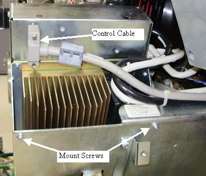
- Disconnect the control cable from the backside of the ADM assembly.
Figure 1. Axial Drive Module Rear View
- Remove Axial Drive Module (ADM) front cover by loosening the two (2) thumb screws and sliding the cover up and off the drive module.
- Disconnect the 3 phase VAC power connections at TB1 R, S, T.
Check to make sure cables are labeled otherwise write down colors
for later reference. See Figure 2 for this and subsequent steps for terminal block
locations.
Figure 2. Cable Connections
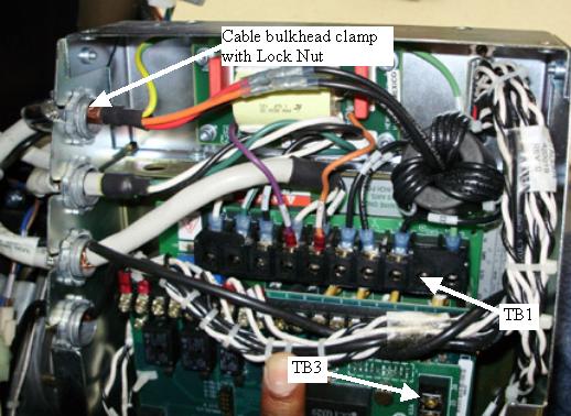
- Disconnect the output PWM cable to the motor at TB1 U, W, V. Check to make sure cables are labeled otherwise write down colors for later reference.
- Disconnect the Axial Dynamic Brake cable connections at TB1 DC+, DC- and TB3 24, 25. Check to make sure cables are labeled otherwise write down colors for later reference.
- Using a flat-blade screwdriver, carefully loosen and fully remove the lock nuts from the Cable bulkhead clamps (4 total). Reference Figure 2. With the lock nuts removed from the bulkhead clamp, slide the bulkhead clamp out of the sheet metal side and pull the cable up through the slots such that the cables are now free from the Drive Module housing. Carefully cut and remove cable ties as needed.
- Disconnect the molex connection at the holding brake relay between the drive module and the axial motor.
- Remove the six (6) M4 screws using the 3 mm hex key. Four (4) screws are on the back side (gantry right side) and two (2) are on the side near the holding brake/motor. Reference Figure 1. This will separate the ADM assembly, including the two (2) trapezoid shaped support brackets, from the main support bracket.
- Verify the two (2) jumpers are in the 5V encoder position on
the new ADM assembly (see Figure 3).
Figure 3. Axial Motor Drive Encoder Board Jumpers
- Assemble the new Axial Drive Module in reverse order. Remember to replace all removed cable ties.
- Remove LOTO to restore system power but do not turn on the gantry service switches yet.
- Install the front, rear top and left side gantry covers.
Refer to
- Enable 120 VAC HVDC and Axial Drive service switches from the service switch panel. Press the table drives enable button on the lower right corner of the service switch panel.
- Install the gantry right side cover.
Finalization
- Perform the Gantry Rotation Safety Check.
- Perform gantry rotational testing using Axial Functional Diagnostic.
Service Desktop>Diagnostics>Axial Functional.
Perform one (1) pass each "Open Loop Rotation" at each scan speed. Verify no errors.
Perform one (1) pass each "Closed Loop Rotation" at each scan speed. Verify no errors.
Perform several passes of "Goto Position" choosing different angles. Verify no errors.
- Perform a Fastcal from the Daily Prep screen on the operator console.