- Topic ID: id_15460708
- Version: 2.0
- Date: Nov 8, 2018 1:38:04 AM
Axial Drive Holding Brake Replacement
Prerequisites
Overview
This procedure defines the steps necessary to replace the Axial Drive holding brake assembly.
Procedure
- Move the table to the home position.
- Remove gantry right side cover.
Refer to
- Turn OFF the Axial Drive and HVDC switches on the gantry’s Service Switch Panel.
- Rotate the tube to the 6 o'clock position.
- Turn OFF the 120 VAC switch on the gantry’s Service Switch Panel.
- Remove the gantry left side cover, top covers and front and rear covers.
 danger
- Perform all required LOTO activities to remove all power from the gantry.
- danger
- Engage indexer lock to prevent unexpected gantry rotation.
- Remove the gantry tilting frame safety side panel next to the Axial Drive components (5 screws, 5 mm hex wrench).
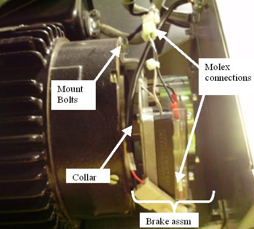
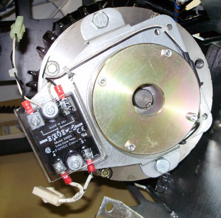
- Disconnect 2 MOLEX connections to holding brake relay.
Figure 1. Axial Holding Brake Assembly
- Remove the Axial Drive Module using the Axial Drive Module Replacement for instructions.
This will provide easier access to the brake module. note:
You may not need to disconnect the cabling to the Axial Drive Module if you shift it up from its current position after removing the mounting screws and fasten it to the gantry frame for safety and to keep it out of the way.
- Remove the 2 bolts that secure BRAKE motor to MOTOR.
Figure 2. Axial Holding brake
- Slide assembly off shaft.
- The new brake assembly comes with a new collar. If any damage
or wear is seen on the existing collar, replace it using the following
steps.
-
Remove the collar by loosening set screw and sliding the collar off the motor shaft.
-
Remove the new collar from the new brake assembly and slide it onto the shaft. Loosen the set screw if necessary.
-
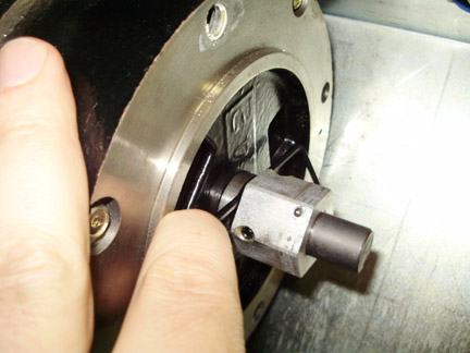
Collar must be positioned 4 mm from the Motor Assembly. Position the collar on the shaft such that a 4 mm hex wrench is snug between the collar and the motor assembly. See Figure 3. The spacing is from the flat sides of the hex wrench, not the corners so the gap is no more than 4 mm.
Figure 3. Collar to motor spacing
-
Leave the 4 mm hex wrench in place when tightening the set screw to maintain spacing.
-
Tighten the set screw to the following torque value:
-
- Install new brake and torque the mounting screws to the following
Torque value:
- Install the Axial Drive module using the Axial Drive Module Replacement. instructions.
- Reinstall the gantry tilting frame safety side cover using the 5 screws and a 5 mm hex wrench.
- Disengage the indexer lock to allow the gantry to rotate.
- Install the front, rear, top and left side gantry covers.
Refer to
- Remove LOTO lock(s) and restore power to system.
- Enable 120 VAC HVDC and Axial Drive service switches from the service switch panel. Press the table drives enable button on the lower right corner of the service switch panel.
1 Finalization
|
- Perform the following Axial Brake Check.
Toggle the axial drive enable switch on the Service Switch Panel. Listen to the brake; it should energize and de-energize.
note:The brake may not toggle if the system underwent a hardware reset since the last time you turned on gantry AC power. If the brake doesn’t toggle, use the 120 VAC enable switch to turn gantry 120 VAC power off, then on. Then toggle the axial drive enable switch. You should now hear the brake as it energizes and de-energizes.
Make sure:
-
When you turn off the axial drive enable, the brake releases. (You can easily rotate the Gantry by hand.)
-
When you turn on the axial drive enable switch, the brake energizes and the gantry stops any rotation previously started by hand.
-
- Make sure Axial Drive, 120 VAC and HVDC service switches are on then, install the gantry right side cover.