- Topic ID: id_15460246
- Version: 2.0
- Date: Nov 8, 2018 1:37:11 AM
(12HW14.6) LightSpeed VCT GOC5 Load From Cold
Prerequisites
Overview
The following procedure describes and illustrates the system software loading process commonly referred to as the Load From Cold (LFC). It is important to follow the steps listed below in order.
These instructions and procedural flow are structured for performing a Load From Cold on a system with the same version software. In other words, a reload of the same software release. If the system being loaded is running an earlier release of software, refer to the Software Upgrade procedure in the Field Modification Instructions (FMI) for the appropriate software release. Additional instructions may be needed when upgrading software, and this information will only be found in the FMI instructions.
12HW14.6 software revision supports Dose Check feature/functionality on LightSpeed VCT GOC5 Operator Console.
1 Software Deliverable for VCT GOC5 Series Consoles
Procedure
- Host CTT Operating System, Version 5.3.11
- CT Applications Software
- DARC CTT Operating System, Version 6.3.11
2 Pre-LFC Checks and Information Gathering
Procedure
- Confirm that a current System State Backup Media is on site.
If unsure of the status of the System State, execute (12HW14.6) VCT GOC5 System State Save Restore procedure found in the Software Chapter of this manual. Save a
System State Backup to either DVD-RAM or USB Media.note:
Only one USB storage device is permitted to be mounted on the Host subsystem of the Operator Console at any given time. When saving or restoring System State to USB media, make certain that only one USB storage device is plugged in. The last USB Storage device pulled into the console will be the mounted device. Possible devices: USB Memory Stick, Customer USB External Storage Drive, SSA Service Keys.
- Remove all media from MOD and DVD Peripheral Towers before starting the OS Load of the LFC process.
- Check network interface status of DARC and IGs.
- Open a Terminal Window on system and log on as root.
Type: {ctuser@hostname} su - and press Enter.
Type the root password and press Enter.
- Run the “nmap” Tool Command on both Host and DARC
Computers:
Assuming the Host Computer is able to boot the operating system and terminal window session is possible, the “nmap” command can be executed to check network interfaces. Note: Failure to communicate with the DARC computer will preclude any further testing of the IGs.
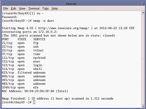
To test network interface between Host and the DARC Computers type: [root@hostname] nmap –n darc and press Enter.
The DARC computer physically configured on the console in question should respond to nmap command (See example below).
Example “nmap” command output from a LightSpeed VCT GOC5 console:
Figure 1. Host Computer “nmap –n darc” Command Output
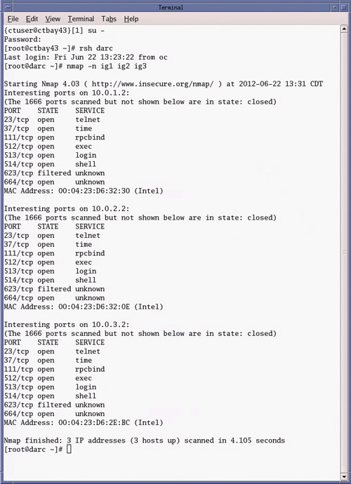
To test network interface between DARC and the IG Computers type: [root@hostname] rsh darc and press Enter.
Type: [root@darc] nmap –n ig1 ig2 ig3 and press Enter.
The IG computers physically configured on the console in question should respond to nmap command (See example below).
Example “nmap” command output from a LightSpeed VCT GOC5 console equipped with three (3) IG computers:
Figure 2. DARC Computer “nmap –n ig1 ig2 ig3” Command Output
- If a computer doesn’t respond, one may try: 1. Power
Cycle on Operator Console or 2. A “reconfig” to rule out
any issues with DHCP Configuration (IP Leasing). If no response after
“reconfig”, one will need to troubleshoot the network
cables and switch and possibly replace the computer hardware in question.
Note: Above tests assumes that the Host and DARC are booted and the
operating systems are accessible. If software corruption is suspected,
proceed with LFC. but understand that the network interfaces have
not been proven functional.
- Open a Terminal Window on system and log on as root.
- Check Exam Split Type.
Type swokinstall -p
If Exam Split option is displayed, execute the following
Type ls –l ~ctuser/ves/.hesMode
If there is .hesMode file, it’s HES mode.
If not, It’s VES mode.
This will be used at reinstall option.
3 Operating Software (OS) Load
Procedure
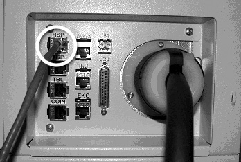
- Unplug the Hospital Network cable from rear Console bulkhead.
Figure 3. GOC5 Rear Bulkhead Panel – Hospital Network Cable Location
- Remove the Operator Console front cover.
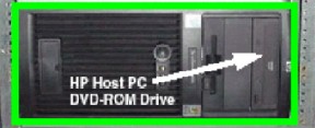
- Insert the Host OS Disk into the Host Computer DVD Drive. See
the following illustrations.
Figure 4. GOC5 Host Computer DVD Drive Location
- Shutdown and Power Cycle Operator Console:
- Using the toolchest, open a Terminal Window.
-
Type: {ctuser@hostname}halt and press Enter.
-
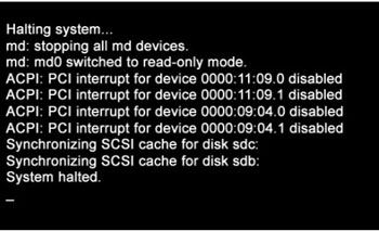
Wait for System Halted message to appear on the monitors.
Figure 5. Monitor Display – System Halted
-
- Turn Off Operator Console power. Wait 60 seconds, then turn power On.
- Using the toolchest, open a Terminal Window.
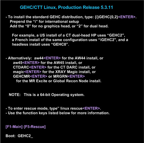
- As the Host Computer restarts, the boot process messages appear. After the booting process completes the boot: prompt appears.
- At the “boot:” prompt, type the following:
Type: boot: GEHC2
Figure 6. Monitor Display – Boot Prompt
- After the Host OS is loaded on the Host Computer, the Complete
window appears.
Figure 7. Monitor Display – OS Load Complete
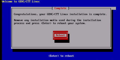
- Remove the Host OS Disk from the Host Computer DVD drive when it ejects and close the tray. Press Enter to Reboot.
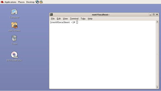
- The Host Computer begins to reboot.note:
Do not insert the Host Applications Software DVD into the Host Computer until the Host Computer has completed rebooting and a Terminal Window appears, displaying the prompt: [root@localhost ~]#.
Figure 8. Terminal Window – After OS Load and Reboot
4 Host Applications Software (APPS) Load
Procedure
- Open the tray on the Host Computer DVD Drive.
- Insert the Applications Disk into the DVD Drive and close the
tray.note:
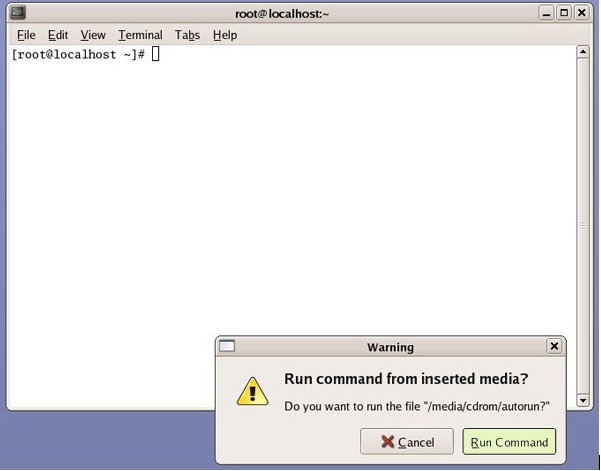
The Applications Disk will open and run automatically.
- Select Run Command in the Warning box.
Figure 9. APPS Run Command Window
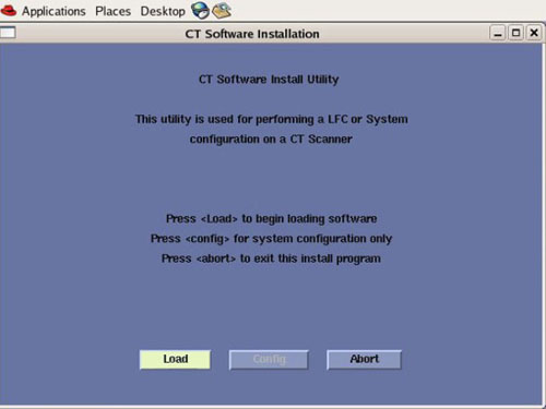
- Select Load in the CT Software Installation
window.
Figure 10. Apps Load Command Window
- System State decision for Install INFO decision box will appear. Select Yes.
Figure 11. Install INFO Window
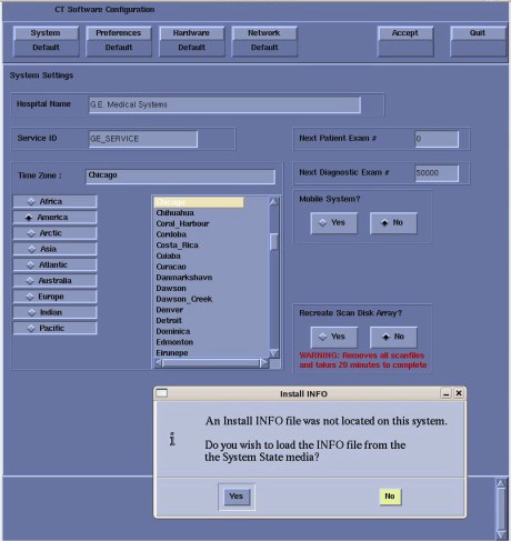 note:
note:If a valid and current System State Backup media is not available, answer No and manually configure the Hardware Tab to define System, DAS, Console and Table type.
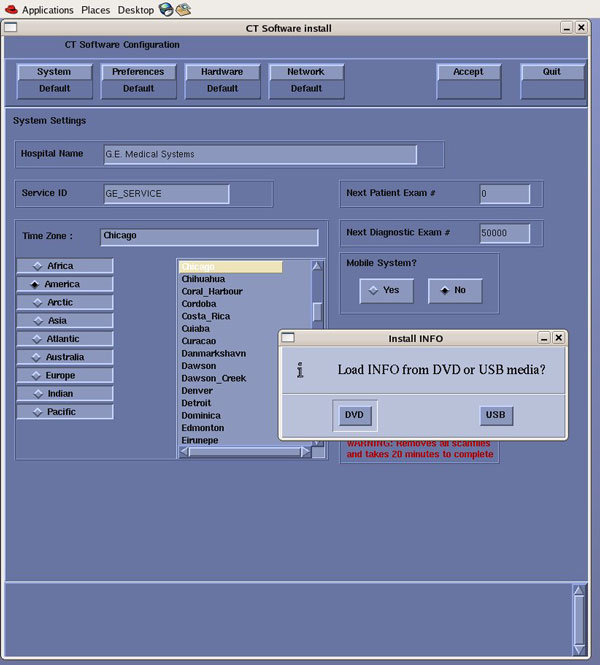
- System State (Install INFO) Media Type decision window will
appear
Select DVD or USB based on media type available.
Figure 12. System State Media Type Window
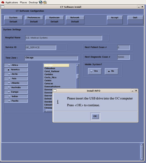
- Insert the System State Backup Media (DVD-RAM or USB). note:
DVD-RAM Media: Insert DVD-RAM Media into the DVD-RAM Drive located in the SCSI Drive Tower.
USB Media: USB Media can be inserted in any of the USB ports located on the console. Recommend using the Service USB port located next to the console's power switch.
Select OK.
Figure 13. Install INFO - System State DVD Install Window
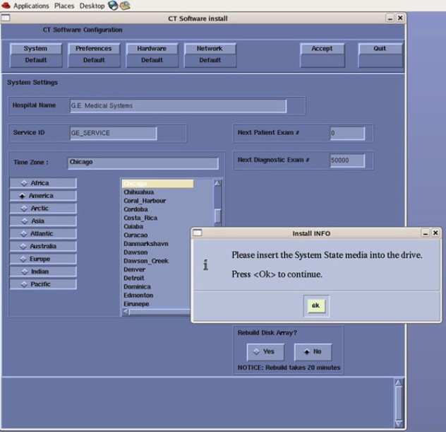
Figure 14. Install INFO - System State USB Install Window
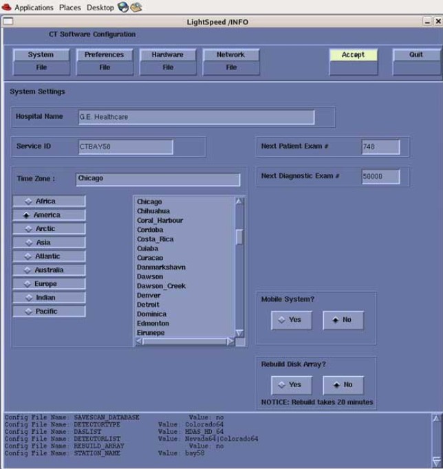
- The Install INFO on the System State Backup Media will be read
and if a valid System State Backup has been inserted, an LightSpeed
/INFO window will become active.
Select Accept.
Figure 15. Install INFO - Accept Window
- The Install INFO on the System State Backup Media will be displayed
and a confirmation window will appear.
Select Yes.
Figure 16. Install INFO - Confirm Window
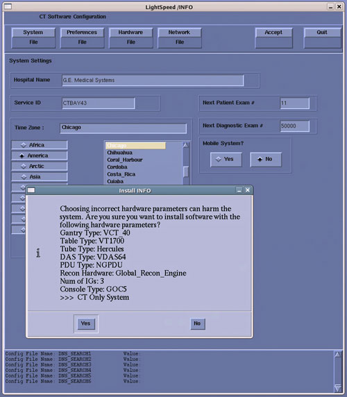 note:
note:Install INFO detail in illustration will differ depending on System type. Verify that the Install INFO detail is correct for the system before selecting [YES].
- System Install INFO will be now used to create the CT Host Application load routine. Do not remove the Host Apps Disk until completed.
- When completed, the Operator Console will automatically reboot.
- After the Host Computer reboots, a pop-up window will appear
Figure 17. CT Software Auto-Start Disabled Pop-Up Windows
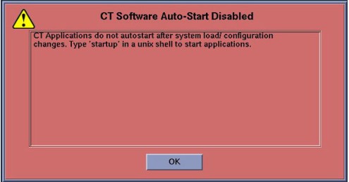
Click OK to close window.
note:Remove Applications disk from Host Computer.
Remove System State Backup Media for either DVD-RAM drive or USB port.
5 LFC Menu - LightSpeed VCT GOC 5 Console Software Load
Procedure
- To launch LFC Menu, open a Terminal Window, and log on as root:
- Type: {ctuser@hostname}su - ENTER
- Type the root password and press ENTER
- Type: [root@hostname] /usr/g/scripts/LFC/startLfcMenu.sh ENTER
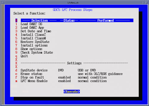
- A window will be displayed showing the LFC Menu. note:
The LFC Menu Utility provides the tools necessary to complete a LFC process without the use of the Linux Command Line. For more detailed information on the operation of this menu click here: LFC Menu Tutorial
In the event an error occurs stating the “rpm package failed to load” during the following steps, clear the “failed” message in the LFC Menu Status and repeat the LFC menu item. If persistent errors occur, the “rpm” packages (install files) may not of copied correctly from the OS or Application (APPS) Disks to the Host PC’s hard drive during the load. The disks may be dirty, damaged, or corruption occurred during the file transfer from the disks to Host PC. To recover, try cleaning the disks or obtain a new copy and restart the LFC from beginning.
Keyboard Control C Functionality:
Using CTRL + C keys to abort LFC process or to close any shell and/or pop-up windows will cause the LFC Menu to display a fault condition for the selected process step.
Windows must be closed with either: a) Right click the window title bar, then selecting Destroy from the menu. b) Left click the icon on the upper left corner of the window, then selecting Close from the menu.
LFC Menu Settings:
By default the System State (SysState) Device setting is configured for DVD. If using USB Media, change SysState Device Setting to “USB” by selecting LFC Menu “d”
Figure 18. LFC Menu Window
- Select Load DARC OS (Menu Selection # 1)
-
Insert DARC OS Disk in Host DVD drive.
-
Select Load DARC OS (Menu Selection #1)
-
Select Execute, a shell window will open and the DARC OS software will be loaded.
-
Click OK on the Pop-up window.
-
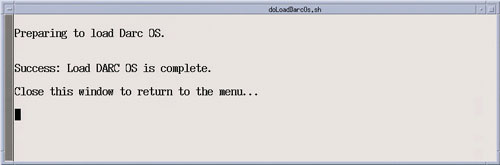
Upon completion of the DARC OS software load, close the execution shell window to return to the LFC Menu.
-
Remove the DARC OS Disk from Host DVD drive.
Figure 19. LFC Menu - Load DARC OS Selection
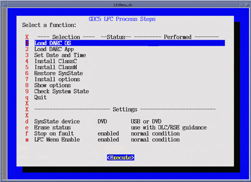
Figure 20. Load DARC OS Execution – Attention Pop-up
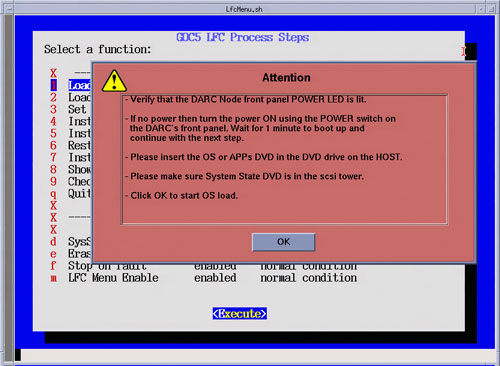
Figure 21. Load DARC OS Execution – Shell Window
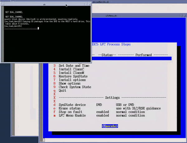
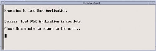
Figure 22. Load DARC OS Execution – Load Completion
-
- Select Load DARC App (Menu Selection # 2)
-
Insert Applications Disk (Same disk used to load Host Applications) in Host DVD drive.
-
Select Load DARC App (Menu Selection # 2)
-
Select Execute, two shell windows will open and the DARC App software will be loaded.
-
Upon completion of the DARC App software load, close the two execution shell windows to return to the LFC Menu.
-
Remove the Applications Disk from the Host DVD drive.
Figure 23. LFC Menu - Load DARC App Selection
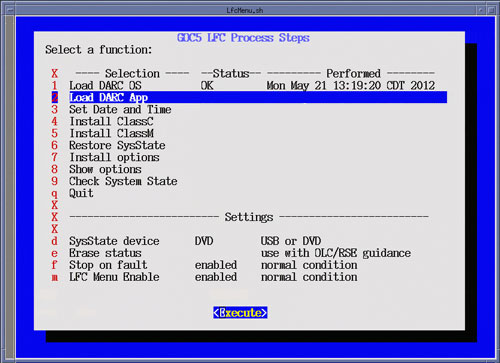
Figure 24. Load DARC App Execution – Shell Window
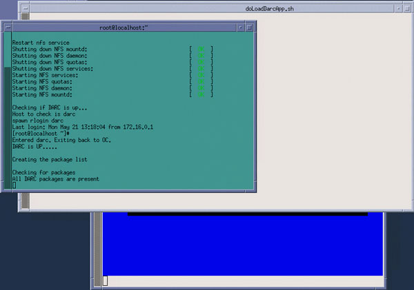
Figure 25. Load DARC App Execution – Load Completion
-
- Select Set Date and Time (Menu Selection # 3)
-
Select Set Date and Time (Menu Selection # 3)
-
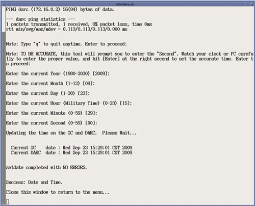
Select Execute, the Set Date and Time Utility will open in a shell window.
-
Follow on screen instructions for setting the correct date and time.
-
Upon completion of the Set Date and Time Utility, close the shell window to return to the LFC Menu.
Figure 26. LFC Menu - Set Date and Time Selection
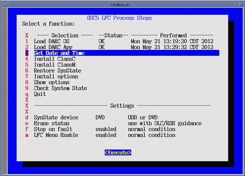
Figure 27. Set Date and Time Execution
-
- Select Install ClassC (Menu Selection # 4)
Selecting this item performs install of Advanced Service Software. (Not required for System operation.) Skip step if not applicable.
note:Class C Advanced Service software applies only to GE Healthcare personnel and customers with an Advance Service Limited License agreement.
- Select Install ClassM (Menu Selection # 5)
Selecting this item performs install of Advanced Service Software. (Not required for System operation.) Skip step if not applicable.
note:Class M Restricted Service software applies only to GE Healthcare personnel.
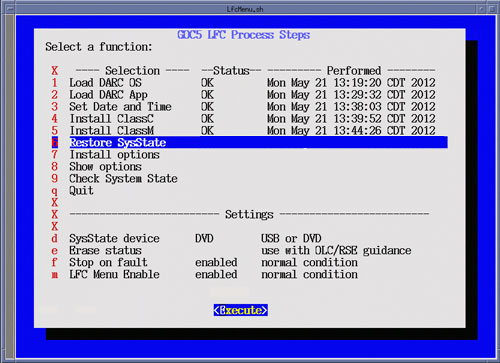
- Select Restore System State (Menu Selection # 6)
-
Insert the System State Media in either the DVD-RAM Drive of USB Port depending on media chosen earlier in this procedure, then select Execute.
-
A shell window will open and the System State will be restored. Several pop-ups will appear requesting configurations settings based on Options being restored. Select appropriate settings for the Options.
-
Upon completion of the Restore System State, a pop-up will appear reminding that a reboot will be required. Click OK, but do not reboot at this time. Close the shell window to return to the LFC Menu.
note:When this menu selection is chosen, the System State Save and Restore Utility will be launched. See (12HW14.6) VCT GOC5 System State Save Restore procedure in the Software Installation section of the Software Chapter in the Service Documentation for more details.
If previously installed, all Options will be restored during the Restore System State.
Remember to set LFC Menu Settings (Selection “d”) to USB if using USB Media. LFC Menu is defaulted to DVD-RAM.
Figure 28. LFC Menu - Restore System State Selection
-
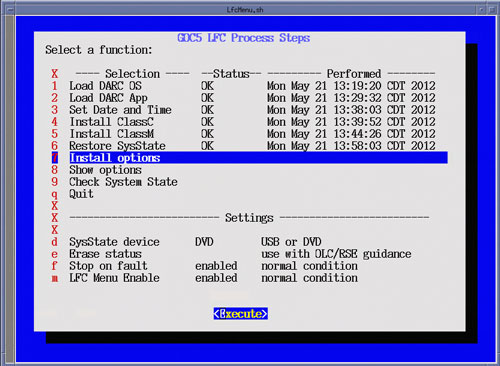
- Optional Menu Selectionsnote:
Install Options (Menu Selection # 7)
If this menu selection is chosen, the Install Software Options Utility will be launched. This menu selection is only required when a valid System State is not available. (Valid means: Current and Created after Options were loaded on system) If a valid System State was restored in the previous step “Restore System State”, this step may be skipped.
After selecting Execute, a shell window will open and the Install Software Option Utility will be launched. Upon completion of the Install Software Options Utility, a pop-up will appear reminding the user that a reboot will be required. Click OK. Close the shell window to return to the LFC Menu.Figure 29. LFC Menu - Install Options Selection
 note:
note:Show Options (Menu Selection # 8)
If this menu selection is chosen, the system will display all installed Options. This menu selection should be used to verify that all applicable Options are installed.
After selecting Execute, a shell window will open and the current installed Options will be displayed. Upon completion of the Show Options, close the shell window to return to the LFC Menu.Figure 30. LFC Menu - Show Options Selection
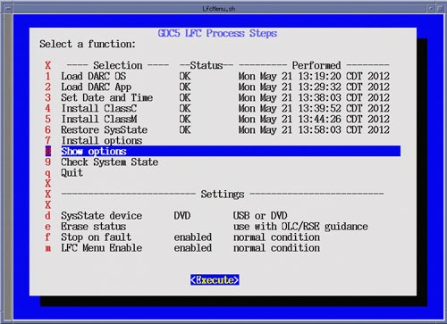
Figure 31. Show Options Execution Example
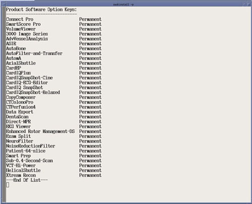
* Example only. Customer specific. Options displayed will be differ system to system.
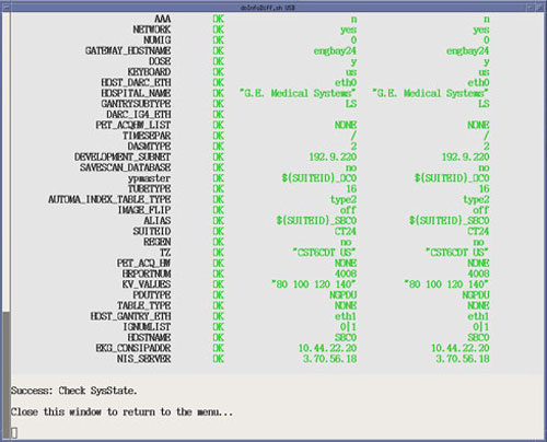
note:Check System State (Menu Selection # 9)
If this menu selection is chosen, the system will display the differences between the INFO file on the System State media to the INFO file on the system. Any differences are identified in RED. If any difference are shown, either a new System State should be save upon completion of LFC or further feature configuration may be needed. This selection requires the System State media to be inserted in the applicable device (USB Port or DVD-RAM Drive) prior to executing selection.
After selecting Execute, a shell window will open and the System State Comparison List will be displayed. Upon completion of the Check System State, close the shell window to return to the LFC Menu.Figure 32. LFC Menu - Check System State Selection
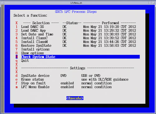
Figure 33. Check System State Execution Example
- Select Quit (Menu Selection # 10)
-
Select Execute, the LFC Menu will check that the minimum procedural steps required for a LFC have been completed.
-
If all LFC Menu selections have been completed, the LFC Menu will terminate.
-
If some of the LFC Menu selections have been skipped, a pop-up window will appear confirming LFC Status.
-
Click Yes if satisfied that all necessary LFC Menu selections have been completed.
Figure 34. LFC Menu - Quit Selection
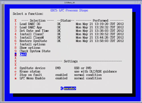
Figure 35. LFC Menu Quit Execution Confirmation Window
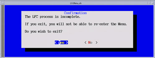 note:
note:The “LFC process is incomplete” message in the LFC Menu Quit Execution Window appears whenever a LFC Menu selection has been skipped. Not all selections require execution. This execution check is only meant to confirm the User's desire to terminate the LFC Menu when selection have not been executed.
Selecting this menu item will terminate the LFC Menu. Only select this menu selection once all steps have been completed.
Once the LFC Menu is turned off (either by confirming the “Quit” Process selection or by disabling the LFC Menu in the LFC Menu Settings), it will remain disabled. To turn the LFC Menu back on will require the following command string to be entered in a Linux Terminal windows:
Open a Terminal Window, and log on a root.
Type:
[root@hostname] /usr/g/scripts/LFC/startLfcMenu.sh ENTER
-
- Reconnect the Hospital Network cable at the rear of the Operator
Console (J26) that was disconnected at the beginning of the LFC.
- Reboot the System
In the Terminal Windows used to launch the LFC Menu, type:
[root@hostname] reboot ENTER.
Allow the System to come up fully into Application Mode. If the CT Applications fail to start automatically, open a Terminal Window and type:
{ctuser@hostname} st ENTER.
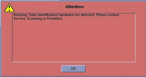
Notice:
When system has Performix VCT Plus (LB) Tube, the following pop-up is displayed after application start up.
Figure 36. Attention Window
6 Tube Install Certification
Procedure
- Perform the Tube Install Certification procedure.
- When completed, continue with Flash Download.
7 Flash Download
Note: Flash Download should be performed as part of any Load From Cold process. In the event a Service Pack load is required for this release, hold off from performing the flash Download until the Service Pack has been installed. See Finalization Section at the end of the procedure.
Procedure
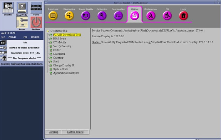
- Perform the Flash Download Utility found on the Common Service
Desktop – Utilities Tab, select Flash Download.
Figure 37. Common Service Desktop – Utilities Tab, Flash Download
 note:
note:The Flash Download takes 5 - 30 minutes, depending on which subsystems need firmware updating.
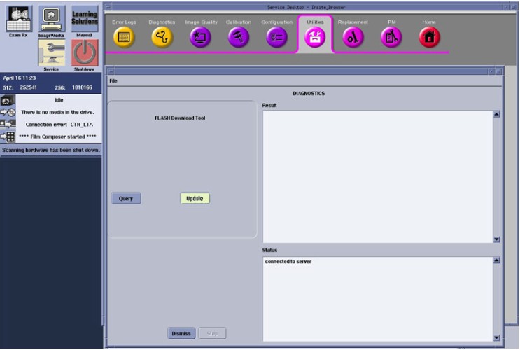
- When the Flash Download Window opens,
Select Update.
Figure 38. Flash Download Window
- Once the Hardware Flash Downloads successfully, select Dismiss.
- Close the Common Service Desktop.
- Select Shutdown icon on the Desktop and restart the system.
8 Service Pack Installation
Procedure
- Service Pack 2.2 must be installed when LB tube is installed.
Refer to Service Pack 2.2 Installation Procedure.
Notice:
Service Pack 2.2 must be installed at this case, in order to prevent fatal damage of X-ray tube.
In other cases, install SP1.1. Refer to Service Pack 1.1 Installation Procedure.
9 Final Save System State
Procedure
- Perform the (12HW14.6) VCT GOC5 System State Save Restore procedure and save a System State Backup to either DVD-RAM or USB Media.
- Save the System State Backup media in a safe and secure location
for future service activity.
10 Finalization
Procedure
- If applicable, install Service Pack updates, refer to the latest Service Pack installation procedure.
- For Japanese language setting system only, perform the following
procedure.note:
If this procedure is not followed, wrong character will be indicated on Network History window in Image Works.
- Open a Terminal Window.
- Type : cd /usr/g/ctuser/terra/resources/nwui
- Type : mv nwui_ja_JP.properties nwui_ja_JP.properties.lfc
- Type : cp -p nwui_en_US.properties nwui_ja_JP.properties
- Open Image Works → Network → Network History and check if all buttons in the Network History window are correctly displayed.
- Reinstall Console Front Cover.