|
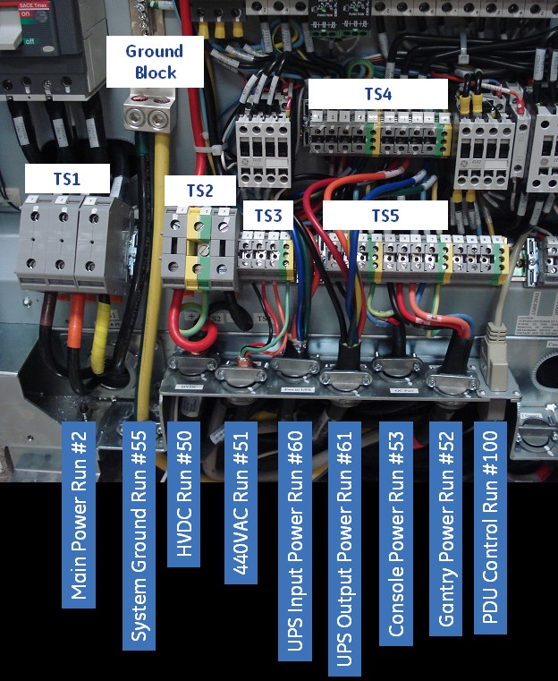
1. Verify power is tagged and locked out at the main
disconnect panel. Verify electrician has completed power connections
to the TS1 panel.
|
|
|
2. Place the circuit breakers in the off/down position
during installation.
|
|
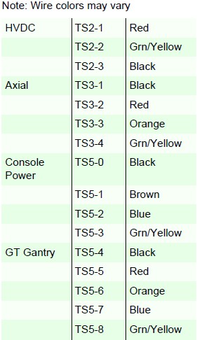
3. Connect the HVDC cable (Run #50) to TS2.
|
|
4. Connect the 440VAC cable (Run #51) to TS3.
|
|
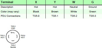
5. Connect the console power cable (Run #53) to TS5-0
through TS5-3. Carefully remove the power plug from the console end.
Verify the plug connections match the PDU connections by comparing
colors.
|
|
|
6. Connect the gantry power cable (Run #52) to TS5-4
through TS5-8.
|
|
|
7. Connect the PDU control cable (Run #100) to J1 on
the A panel.
|
|
8. Connect the ground cable (Run #55) from the table/gantry
raceway ground bus to the PDU ground block.
|
|
9. For installations with a UPS option: Remove all three
terminal jumpers from TS4. Connect the UPS input power cable (Run
#60, P/N 5125079) to TS4-1 through TS4-5. Connect the UPS output
power cable (Run #61, P/N 5125079-2) to TS4-6 through TS4-10.
|

