- Topic ID: id_15460624
- Version: 2.0
- Date: Nov 8, 2018 1:36:22 AM
PDU Cable Connections
1 PDU Cable Connections & Configuration
|

2 Introduction to NGPDU
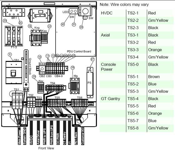
As seen in Figure 1, a number of cables must be installed throughout the PDU. Specific details on each connection can be found in the sub-sections that follow. Use Figure 1 for reference. The PDU has been designed to have cables routed into the PDU from behind and/or beneath it.
Figure 1. PDU Cable Connections - Front
3 Panel - 380 - 480VAC Mains “TS1” Input Power Connection
-
If present, remove the TS1 panel front cover.
-
Strip the wires to fit securely on the power block.
-
Observe incoming phases (L1, L2, and L3) and insert bare leads into power block.
-
Insert vault ground into PDU vault ground lug.
-
All connections on the PDU should be torqued per these tables:
4 Panel - Circuit Breakers
Place the circuit breakers in the off/down position during installation, even with mains incoming power tagged and locked out. After you have completed work on the PDU, you may return the circuit breakers to the ON positions.
Figure 2. Circuit Breaker Panel
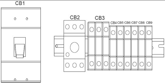
By design, when CB3 is in the OFF position, circuit breakers 4, 5, 6, and 7 are switched OFF. CB3 is essentially in series with these breakers.
5 HVDC Connection
Refer to Table 3.
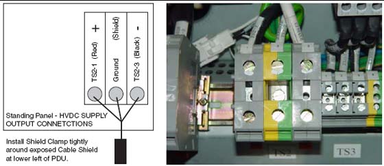
Connect the internally shielded HVDC cable to TS2 on the standing panel (See Figure 1 for the location of the connector and Figure 3 for details). Observe polarities and grounds. Do not cut or shorten cables unless you have all of the appropriate tools and crimper to re-terminate. If short cables are needed, have the PMI order the short cable set.
 |
|
Figure 3. HVDC Connection
6 440V Connection
Refer to Table 3.
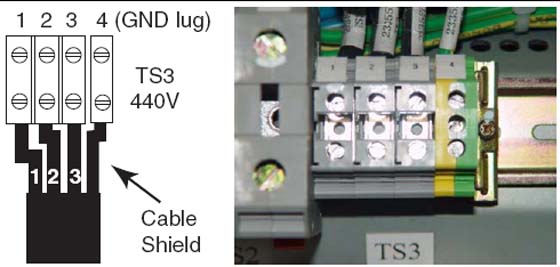
Connect the internally shielded HVDC cable to TS2 on the standing panel (See Figure 1 for the location of the connector and Figure 3 for details). Observe polarities and grounds. Do not cut or shorten cables unless you have all of the appropriate tools and crimper to re-terminate. If short cables are needed, have the PMI order the short cable set.
|
|
Figure 4. 440VAC Connection
7 GOC6 Console & Gantry Power Connections
Refer to Table 3.
Do not cut or shorten cables unless you have all of the appropriate tools and crimper to re-terminate. If short cables are needed, have the PMI order the short cable set.
|
|
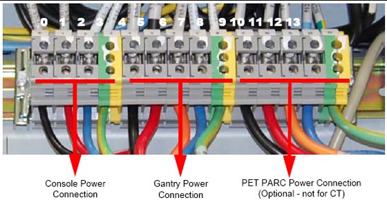
Plug the gantry power cable wires into J4 and the Console power cable wires into J5 as shown in Figure 5.
Figure 5. Gantry & Console Power Connections
8 Console Power Cable Plug Removal
Power cable re-termination is not allowed. Short and long cables are available.
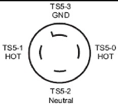
Carefully remove the power plug and record the color of the wires in Table 4. The terminals are labeled X, Y, W, and G on the plug.
Figure 6. Console Power Plug
9 Console Power Connection
The console can only be powered from this connection.
10 PDU Control Cable
The PDU control cable comes pre-terminated and should not be re-terminated in the field. Excess cable length must be stored. Simply plug the cable into J1 on the A panel. Secure it by using the fasteners integrated into cable’s connector shell.