Route Power and Control Cables between System Components
notice
NOTICE: Potential for Data Loss and/or Equipment Damage
To prevent potential data loss and equipment damage, please do the following:
- Record data collected from procedures in this chapter into Form F4879 when directed.
- Only use the Installation manual that arrives with your system for installation. Any other revisions of this manual may not exactly match your system.
1 Introduction
Site use of conduit, floor duct, wall duct, or a raised computer
floor, as well as the individual component layout determines the system
cable sequence. If your site has floor or wall ducts that will interfere
with placement of the table/gantry, it may be important to have the
movers unload the cable boxes (8 & 9) first and run those cables
while others unload the subsystems.
Try to run the system cables
after the contractor completes the contractor supplied wiring.
All ground wires and other
contractor wiring should be complete to the point of equipment placement.
notice
Potential for Equipment Damage
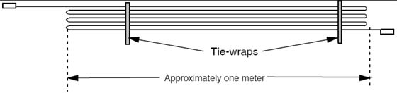
2 Cable Storage
Do not store excess cable in the bottom of the PDU
or Gantry.
Do not store excess cable behind or under the installed components
(table, PDU, gantry or console). Check with the site electrical contractor,
before hiding excess in conduits or cable ducts. Refer to the electrical
code requirements for duct fill rate in your area. Shown on the site
print, the fill rate will meet all requirement when cables are run
point to point without access.
Figure 1. Excess Cable Storage Configuration
Keep signal and control cables away
from power cables and power wiring. When you lay cables in a raceway,
locate the signal cables in a separate section of the raceway, or
a separate conduit.
Check all connections for tightness.
Use suitable tools and judgment.
Check all visible connections, especially
ground connections.
Check for reasonable cable routing.
Take into consideration necessary take-up
distances for equipment maintenance, etc.
Try to complete as neat a job as possible.
3 System Component Identification
Identify all system cables by the system component designators
listed in Table 1. Each end of a system cable has a label, and may
have a color near the connector, (refer to Table 2) to indicate the component and the jack identifier of the component.
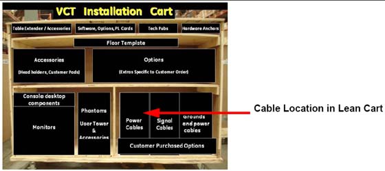
All cables are located on the lower right shelf of the lean cart.
4 Cable Color Identifiers
The ends of the cables may be marked with a piece of blue, yellow,
red, or orange colored tape to help with the cable installation. Table 2 lists the subcomponent, and corresponding color.
If your system is not a lean packed system, locate the boxes
with the system cables. They should match the cables in the following
table.
Figure 2. Cable Location in Lean Cart
Shortening power cables is not allowed. The crimping tool and
ferrules are not shipped with the system.
If longer or shorter cables are required, order the correct
set.
Excess cables cannot be stored under or behind the PDU, gantry
or console.
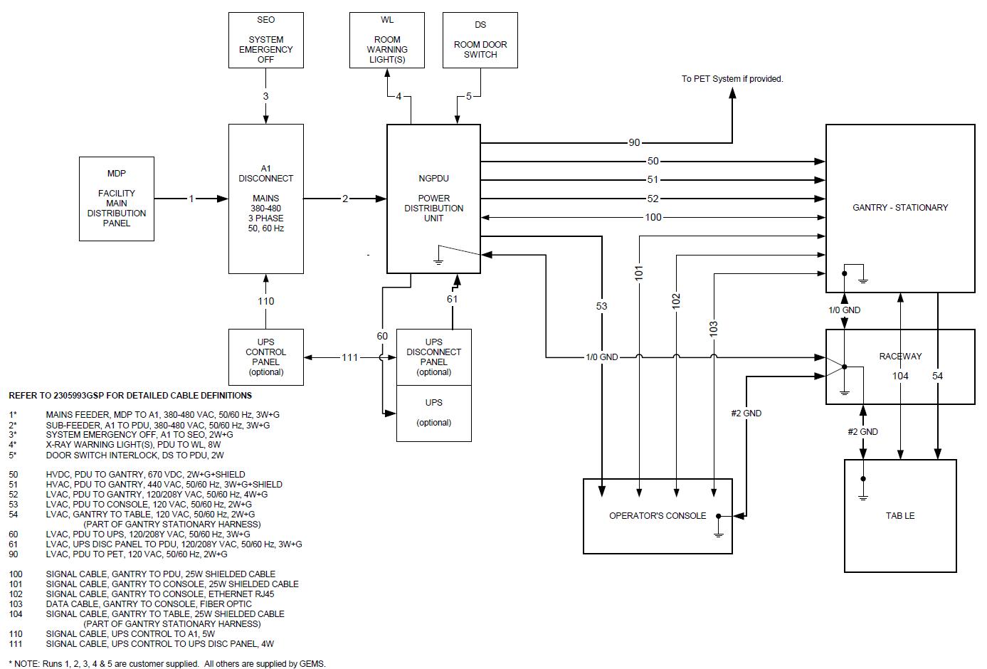
5 System Interconnect Diagram
Refer to Figure 3 for the System Interconnect
Diagram.