- Topic ID: id_15460271
- Version: 2.0
- Date: Nov 8, 2018 1:38:14 AM
FRDM Sulfur Plug Kit Installation
1 Overview
PURPOSE (DETAILED):
The purpose of the FRU kit is to make functional failing FRDMs that have failed by installing the appropriate fix to electrically short failing resistors. Detector models listed below can fail due to certain environmental conditions.
EFFECTIVITY:
-
32/64 detector (L-Fine, Sherlock, HALO, Colorado and Saturn) systems.
-
Affected Products;
-
VCT (64 slices)
-
LightSpeed Pro32 (VCT Select 32 slices)
-
Discovery VCT
-
Discovery 690
-
Discovery CT 750HD
-
-
Affected Detector models;
-
Sherlock Detector : 5126400, 5156400, 5156400-2
-
L-Fine Detector : 5123200, 5153200
-
HALO Detector : 5175283
-
Colorado : 5206300
-
Saturn : 5202100
-
FURNISHED MATERIALS IN FRU KITS:
OPTIONAL TOOL:
2 Procedure
Throughout the Procedure, this document will refer to the Service Methods procedure for the proper procedure steps to SAFELY remove GANTRY COVERS, REMOVE PLENUM and FRDMS and Run necessary DIAGNOSTICS: LightSpeed 7.x Series Service Methods > Replacement > Gantry > DAS and Detector > FRDM Replacement Procedure.
2.1 Preparation for Installing the Fix
This section is for only Sherlock Detector. Other Detector can skip this section.
The following section will prepare the system and a work space for clean plug installation.
-
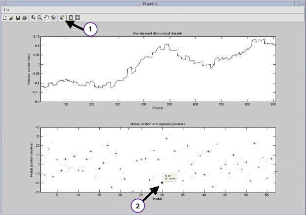
Prior to pulling modules for plug installation it is important to check current alignment to establish a baseline for comparison later. Follow the below steps to review the systems current alignment:
note:If any modules are out of alignment, it is recommended to wait until plug fixes have been completed before correcting alignment.
-
From the Common Service Desktop, Utilities Menu, Open a Shell and type: zalignmentWizardEnter.
note:zalignmentWizard will NOT open from a regular UNIX shell, it must be opened from the Utilities Menu in CSD.
-
The alignment check will run 2 stationary scans and show plots as shown in Illustration below Processing will take approximately 2 minutes after the scans are run.
-
Save as a copy of the output as a jpg in the usr/g/scripts directory.
note:Refer to Direction 5338260-2EN (LightSpeed 7X Series Service Methods) FRDM Replacement Procedure, Section 3.7 for additional information regarding current alignment.
Figure 1. Alignment Check
2.2 Review Baseline for Structured Noise
This test will set a base line for the current system performance.
Reference: LightSpeed 7.x Service Methods (5338260-8EN) Troubleshooting > Diagnostics > DAS Tools (VCT VDAS and HDAS)
-
Select DAS Tools > Auto Test.
-
Set to 1 iteration > Hit Accept.
-
Review graphs: Select View Specifications > QIF Visualization Tools.
For HD system. Instead of QIF Tool, please use “Scan Analysis” to check SD value. CSD -> Image Quality -> Scan Analysis.

- notice
2.3 Clean and Organized Workspace Preparation
-
Locate a clean surface and place an ESD mat to use as a work area. The detector modules are very sensitive to ESD and dust; they need to be handled with care.
-
Clean all work surfaces, including the ESD mat, the work area must start off clean and organized.
-
Ensure ESD strap is on and properly connected. (Gloves are recommended)
-
Gather the following at the workspace.
-
Plugs from FRU kit.
-
Installation Tool
-
Nitrile Gloves
-
2.4 Installing Fix
|

|
|
|
-
Remove Detector Air Plenum from Detector assembly.
Refer to the Detector Air Plenum Removal and Installation procedure on LightSpeed 7.X Service Methods documentation Direction 5338260-8EN.
For Plenum Removal: Replacements > Gantry > DAS and Detector > Detector Air Plenum Removal and Installation.
For FRDM Removal: Replacements > Gantry> DAS and Detector > FRDM Replacement Procedure.
-
Axial Drive and HVDC switch on Service Panel should be disabled.
-
Gantry rotation should be locked with Detector Positioned at 12 o’clock position.
-
-
Plug/Clip Identification and Install Preparation.
note:There are 3 types of J4/J5 connector configurations on the A/D Board, FRDM.
-
GEN1 connectors.
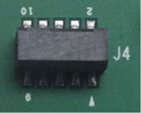
To apply plugs on GEN 1 type connector, the Green Spacer remains on the plug for proper connection. GEN 1 fix is only application for L Fine Sherlock 32 Slice systems. This fix doesn’t apply for Sherlock 64 Slice modules.
-
GEN2 connectors.
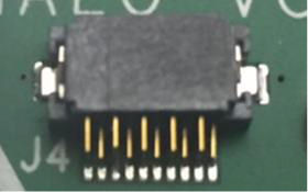
To apply plugs on GEN2 connector, the Green Spacer will need to be REMOVED from the plug prior to application on the board.
-
GEN3 (no connector in J4 / J5 location).
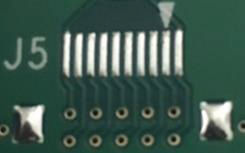
Clip is needed for GEN3. It is only available for L-Fine, HALO and Colorado detector modules.
For Sherlock : These boards will either be NO FIX or require a module replacement if failing.
-
-
Review the Following Illustrations, and then continue with Plug/Clip Installation in Step
Figure 2. GEN 1 Connector - Green spacer remains on the plug
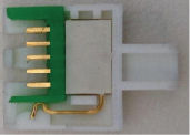
Figure 3. GEN 2 Connector - Green Spacer Removed from the plug.
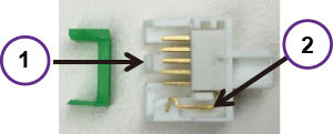
Figure 4. GEN 3 Connector
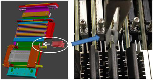
Figure 5. Connector Location
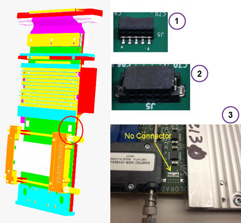
Figure 6. Detector with Plenum Removed
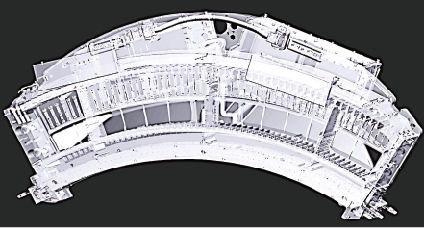
Figure 7. Location of Connectors
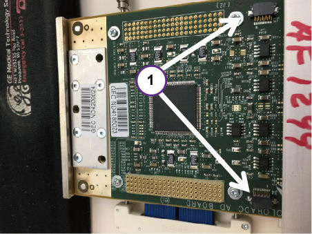
Figure 8. Location of Connectors
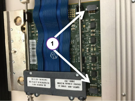
Figure 9. Top of board with plugs installed
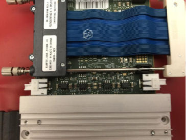
Figure 10. Bottom of board with plugs installed
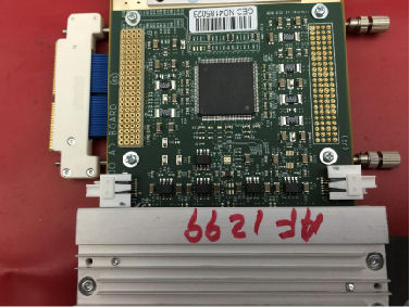
Figure 11. Outer view of board with GEN2 plugs installed
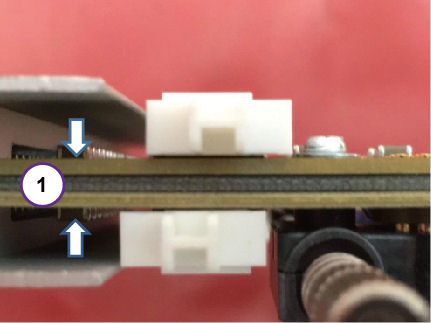
Figure 12. Inner view of board with GEN2 plugs installed
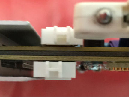
Figure 13. Two boards with GEN2 plugs installed
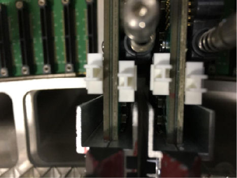
Figure 14. Plug placement using tool provided
Figure 15. View of Clip placement
-
Plug installation
-
For Sherlock 64 modules with GEN2 connector requiring plug installation. Remove one module at a time, vacuum any dirt from connectors and install the plugs per the install guidelines in section 2.4 step 2 and 3, Sherlock Detector will require plugs on both inner and outer side of board and both A/D Modules (both sides) for a total of 4 plugs. Note that if any of the connectors on Sherlock 64 module are GEN1 type, then module will need to be replaced if failing.
L-fine32, Halo and Colorado Detectors will require plugs on only the outer side and plugs can be installed without removing the modules. Halo and Colorado modules will require 2 plugs and L-fine 32 will require 1 plug.
-
Repeat the Plug installation on all other identified modules.
note:Only install plugs on the modules and locations identified as needing repair.
-
-
Clip Installation
If any clips have been designated, install them at this time per the install guidelines in section 2.4 step 2 and 3. Clip installation does NOT require removing modules as clips will only be placed on the outer side. DO NOT install clips on Sherlock 64 modules and instead replace modules if failing.
-
Module Alignment Check (gantry covers off)
If No modules were pulled out, this step can be skipped, go to step 7 Structured Noise Test.
When all modules are completed, check the alignment of the modules. This can be done once, without having to reinstall the plenum. Check alignment by doing the following:
note:For Outer Modules 1-26 and 32-57, only look at the Modules you replaced. Do NOT move other modules. Some Factory modules may not be within this specification.
-
Ensure that the rotational lock is engaged.
-
Ensure that the front display is connected to satisfy e-stop.
-
Apply the HVDC and the 120VAC power ONLY. Do NOT turn on the axial drive. Use the Gantry Rotation Lock to lock out Gantry Rotation.
-
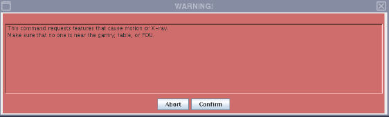
In Common Service Desktop under the Utilities menu, open a Shell window and type: zalignmentWizardEnter.
note:The following window will pop up to indicate X-Ray will be created. Ensure that the gantry is locked and Axial Switch is off, the click Confirm.
note:Be sure to no leave the systems powered up for long without the plenum, this can cause the detector to overheat.
Figure 16. Warning Window
-
The alignment check will run 2 stationary scans and show plots Processing will take approximately 2 minutes after the scans are completed.
-
Refer to: LightSpeed 7.x Service Methods (5338260-8EN) FRDM Replacement Procedure, Section 3.7 step 3 for information regarding current alignment.
-
Make alignment adjustments as needed, typically, the alignment wizard can only be run once without the Plenum and Light Seal Installed. Without the plenum installed, airflow will be altered and the detector may overheat and shut down.
note:At this point, the saved baseline scan from earlier can be reviewed as a reference but it is not necessary. The before and after do not have to match, the ‘after’ needs to be in specification.
-
-
Review Structured Noise test after plug/clip installation.
-
Install Light Seal and Plenum (Can be installed with a minimum amount of screws at this point to ensure it stays in place, but can be taken off quickly if rework is needed. Ensure that AXIAL DRIVE is DISABLED. Use the Gantry Rotation Lock to lock out Gantry Rotation.
-
Run Manual Noise Test
DAS Tools (VCT VDAS and HDAS) > Manual Test > Select 1 Iteration of DC Noise, Offsets, and Structured Noise. > Hit Accept
-
Review graphs: Select View Specifications > QIF Visualization Tools
For HD system, please use “Scan Analysis” to check SD value. If Structure Test fails, turn off power, remove Plenum and Light Seal, recheck plug installation on failing modules.
Ensure that plugs are correctly seated. Then return to Step 6 above to recheck alignment and Structured Noise Test. When Structured Noise is acceptable, continue to next step to close up gantry.
-
2.5 Completely install plenum and light seal
-
Completely Replace Light Seal Cover and cover bands per Steps 3.5.13 and 3.5.14 of (LightSpeed 7.x Series Service Methods > Replacement > Gantry > DAS and Detector > FRDM Replacement Procedure).
-
Completely Re-install Plenum Step 3.6 in FRDM Replacement Procedure.
-
Continue with Detector Testing per Step 3.7 of FRDM Replacement in Service Methods for alignment check with Plenum and Light Seal installed.
-
Reassemble gantry covers per step 3.8 of FRDM Replacement in Service Methods.
2.6 System Calibration
Perform System Calibration per step 3.9 of FRDM Replacement procedure in Service Methods.
If No modules were pulled out, skip steps 1, 2 and 3, Only Fast Cal is required.
To conclude:
-
FRDM Process Tool [Prep for Calibrations] - Only if modules were removed and re-installed.
-
Perform [Collimator Cal] - Only if modules were removed and re-installed.
-
Perform full [Detailed Cal] - Only if modules were removed and re-installed.
-
Perform Fast Cal - Must be done for all.
3 Finalization
-
Perform a Scout Scan and a minimum of 20 Helical or Axial Scans.
-
Close SR or Dispatch include Exam # of the test scan in the Debrief comments.
Note that Exam# for test scan in this step and record that Exam# in debrief comments should say “exam # __________ completed to verify functionality.