- Topic ID: id_16157883
- Version: 3.0
- Date: Nov 27, 2020 2:07:17 AM
Z-Align
Prerequisites
Overview
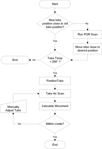
The purpose of the Z-Align procedure is to move the X-Ray Tube to be in alignment with the Detector and Collimator. The Detector and Collimator were aligned with the previous Tube, and Z-Align will correctly place the new Tube in the Z-Direction. The procedure can be summarized as follows:
-
Verify Tube Temperature is less than 200°C
-
Run Beam On Window (BOW) scan
-
Perform Tube Installation Certification, if needed
-
Calculate Z-Align
-
Move Tube
Figure 1. BOW Alignment Process Flow
Procedure
- Run the Beam On Window (BOW) alignment tool, take a scan, and
calculate the movement vectors. See the Beam on Window Alignment procedure for
more details.
Figure 2. Beam on Window Alignment GUI (BB Tube)
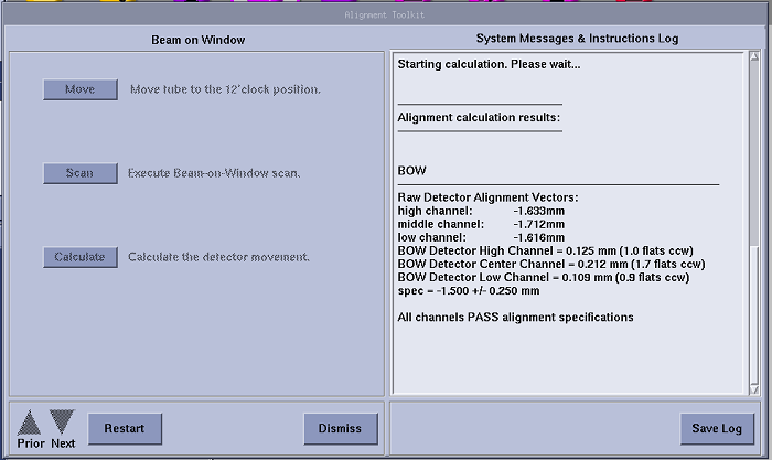 note: Above illustration is only GUI example, each product should have its correct specs shown on the system.
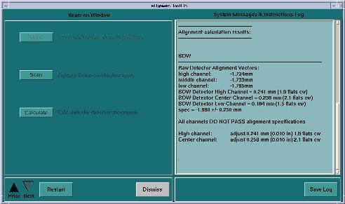
Figure 3. Beam on Window Alignment GUI for BrightSpeed Select systems with a Solarix tube
- Perform Tube Installation Certification, if needed. Refer to SmarTube™ Setup.
- Determine system type. For RT systems, the correction factor
is 1/5.5 -- otherwise, the correction factor is 1/4.85.
- Calculate the z-align movement. (This is the amount that you
will move the tube. The direction will be either forward or backward
[towards the table or the slip ring].)
- BOW Measured = Movement vector for MIDDLE CHANNEL (The High and Low channel vectors can be noted to see that the detector is not skewed, but do not use for tube movement calculation)
- Tube Z movement = BOW Measured / Correction Factor (for either unit, mm or in)
- Move the tube by Z movement value amount in the OPPOSITE direction
that the flats measurement tells you to.
Example:
BOW Movement vectors:
-
BOW high channel: -0.446mm -0.018in
-
middle channel: -0.653mm -0.026in
-
low channel: -0.611mm -0.024in
If the movement vectors are negative (-), move the POR adjuster screw clockwise (CW).
If the movement vectors are positive (+), move the POR adjuster screw counter-clockwise (CCW).
-
(For RT) In this example, you would move the tube 0.119mm (0.005in or 1.04 flats) clockwise (cw). [0.653mm / 5.5 = 0.119mm OR 0.026in / 5.5 = 0.005in.]
-
(For Non-RT) In this example, you would move the tube 0.131mm (0.005in or 1.04 flats) clockwise (CW). [0.653mm / 5 = 0.135mm OR 0.026in / 4.85 = 0.0054 in]
-
- Install a dial gauge for the POR adjustment on the dial mounting
bracket.note: See appropriate tube change procedure for illustration of dial mounting bracket.
- Loosen the tube mounting bolts 1 turn maximum.
- Using the POR adjustment screw, adjust the tube according to your Z-align calculated value.
- Tighten the tube mounting bolts. You should find that tightening
the bolts gradually in a cross pattern will reduce tube shifting during
tightening.note: Exercising patience while tightening the bolts will result in accurate positioning and reduce the number of Z-Align iterations.
- Run another BOW scan to verify that the alignment is within specifications. If it is not, repeat z-align procedure.
- Turn M12 tube mounting bolts to pre-load torque specification
as shown in Table 5.
- Apply final torque on all four M12 bolts according to the values
specified in Table 6.
Finalization
No finalization steps.