- Topic ID: id_11038758
- Version: 2.0
- Date: Jan 30, 2019 9:42:47 PM
Slipring Platter Replacement
Prerequisites
This procedure describes the Slipring Platter replacement.
1 Remove the Old Slipring
Procedure
-
(For European mobile units manufactured by Medical Coaches,
Inc., sometimes known as Medcoach vans) Prepare the scan
room and follow the instructions in Prepare Mobile Scan Room for Component Replacement.note:
Space around the Gantry in a mobile van is very limited. Use caution when lifting and moving the Slipring into and out of the scan room.
- Remove Gantry covers as required.
Refer to
- Remove Slipring safety covers.
- Tilt Gantry forward to +30 degrees.
 danger
- Completely shut down system power. (A1, Lockout/Tagout)
- Remove rear cover mounting brackets, both sides. Three (3) M12 bolts on each mount.
- Remove brush block and tie-wrap the brush block to the stationary
member out of harm's way.
The brush block assembly may be entirely removed if desired.
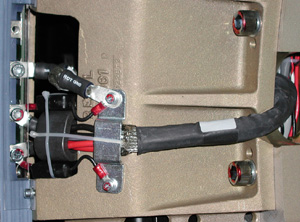
- Remove all wiring tie-wraps on the Ring inside diameter.
-
Write down all filter and cabling connections.
-
Write down tie-wrap locations and sizes.
Figure 1. Slipring Filter
-
- Disconnect all cables from Slipring.
- Remove antenna bracket with antenna assembly.note:
Follow this procedure EXACTLY. Do not take shortcuts. Both axial and radial runout as well as Gantry balance are at stake.
- Rotate Gantry so signal PCB is in 12 o'clock position. This puts the Tube at 12 o’clock also.
- Engage axial rotating lock to prevent Gantry rotation.
- Mark Slipring, Slipring cast mounting brackets, and rotating
casting with numbers 1 through 6.
-
Start at 12 o’clock and write “1” on all three surfaces.
-
Continue clockwise with the next mount with number 2. Do this for all remaining mounts.
-
This will ensure everything will be installed in the same locations.
-
2 Install New Slipring
Procedure
- Open new Slipring box. Put on the gloves.
-
Place top cover on the floor foam side up.
-
Flip the new Slipring over in the box, so that brass is face down.
-
Install the signal PCB.
-
- On the Gantry, remove all twelve (12) M12 bolts securing the
cast mounting brackets to the rotating casting.
Leave the bolts at the 12 o'clock position for last.

- danger
note:Remember there are three (3) mounts with pins, so pull ring straight off. Use a flat-blade screwdriver to separate the brackets from the rotating casting if necessary.
- After removing the last bolts, carefully remove Slipring and cast mounting bracket assembly.
- Place the old ring, brass side down, on top of foam cover.
Align the signal PCB with the replacement ring to simplify the transfer of the cast mounting brackets to the new Slipring.
note:Inspect all interfaces for burrs, debris, or other imperfections. These items can result in runout failures, requiring a repeat of this entire procedure.
- Transfer each of the cast mounting brackets one at a time. Ensure
these brackets are installed in the same position from old to new
Slipring.
- Place cast mounting bracket number 1 on the new Slipring aligning
6 mm pin in slot.
There are four (4) holes that attach the cast mounting bracket to the Slipring. The hole diagonal from the pin is 6.2 mm. The other three are 7mm. The 6.2 mm hole and 6 mm pin are to help align the ring.
- Place the 6 mm bolt in the 6.2 mm hole and align over Slipring insert.
- Gently pull or push the cast mounting bracket radially out (away from ISO). Use the pin slot as the stop and the 6.2 mm hole for alignment.
- Tighten the 6 mm bolt until the lock washer starts to compress. Just tighten (snug) enough so that bolts are engaged.
- Install the other three (3) 6 mm bolts and snug until they are
engaged.
Once the Slipring is installed, set the torque on all of the bolts to:
- Place cast mounting bracket number 1 on the new Slipring aligning
6 mm pin in slot.
- Repeat Step 5 for all six (6) cast mounting brackets.
- Align new Slipring and cast mounting brackets with the rotating
casting.
-
Ensure marked numbers are aligned, 1 to 1, 2 to 2 etc.
-
Align guide pins with holes on each of the three (3) cast mounting brackets to rotating base.
-
Push until seated. Maintain pressure against the ring and hand tighten all M12 bolts.
-
- Release axial rotational lock.
Rotate Gantry by hand as needed to ease access to Slipring mounting bolts.
- Set final torque. Refer to Figure 3.
Start with the three (3) pinned cast mounting brackets.
note:For a larger version of this illustration, click on the PDF icon below.
Figure 2. Full Size Illustration: Slipring Platter Torque Pattern
50154.pdfFigure 3. Slipring Platter Torque Pattern
- Start with bracket location # 1 and set the torque on the two
(2) M12 bolts to:
- Repeat Step 9 for cast mounting bracket # 2 through # 6 in order.
- Start with bracket location # 1 and torque the four (4) 6mm
bolts in order 1, 2, 3, 4. Reference Figure 3.
Set torque to:
- Repeat Step 12 for location # 2 through # 6 in order.
- Connect the filters, wiring harnesses and ground clamps to the Slipring.
- Mount and adjust the Dial Indicator so that the plunger tip rides on the blue edge of the HSDCD ring.
- Rotate the Gantry by hand and measure the Radial Runout.
-
Radial runout should not exceed .0319 inches (32 mils, 0.81 mm).
-
Reference Radial Runout Adjustment, if out of specification.
-
- Adjust the Dial Indicator and place the plunger tip directly on the brass surface of ring 12.
- Rotate the Gantry by hand and measure the Axial Runout.
-
Axial runout should not exceed .0327 inches (33 mils, 0.83 mm).
-
Reference Axial Runout Adjustment if out of specification.
-
- Secure all rotating harnesses with tie-wraps as observed at start of this procedure (Figure 1).
- Install Antenna/Receiver assembly. Reference Slipring Receiver (850MBaud) Replacement.
- Install brush block assembly Slipring Brush Block Replacement.
- Install Slipring safety covers.
- Restore power to system.
3 Radial Runout Adjustment
Procedure
- danger
- Identify the “High” and “Low” physical locations on the Slipring.
- With the gantry tilted forward + 30 degrees, place the “High” location at 12 o’clock.
- Loosen-do not remove-the four (4) 6 mm bolts at the cast mounting bracket to Slipring interface.
- Loosen-do not remove-the four (4) M12 bolts on each of the six (6) cast mounting brackets.
- Physically lift/push/pull the ring to release binding tension.
At + 30 degree tilt, gravity effects are minimized.
- Re-torque bolts per Step 8 through Step 12. Tightening sequences must be followed for desired results.
4 Axial Runout Adjustment
Procedure
- danger
- Identify the “High” and “Low” physical locations on the Slipring.
- With the Gantry tilted forward + 30 degrees, place the “Low” location at 6 o’clock.
- Loosen-do not remove-the four (4) 6mm bolts at the cast mounting bracket to Slipring interface.
- Loosen - do not remove - the four (4) M12 bolts on each of the six (6) cast mounting brackets.
- Physically lift/push/pull the ring to release binding tension.
At + 30 degree tilt, gravity effects are minimized.
- Re-torque bolts per Step 8 through Step 12. Tightening sequences must be followed for desired results.
- notice
- Inspect the one (1) or two (2) closest cast mounting brackets
for proper seating at both the Slipring and rotating casting interfaces.
-
All bolts should be properly torqued.
-
No gaps greater than .005 inches (0.127 mm) at any interface edge.
-
- Correct any “High” gaps greater than .005 inches (0.127 mm) at any interface edge.
- Recheck both Radial and Axial runout.
- Using standard notebook paper (0.003 inches (0.076 mm) thick
nominal) make shims for one (1) or two (2) mounting locations on either
side of the “Low” location.
A single sheet folded in half when compressed will be 0.005 inches (0.127 mm) nominal.
- Remove the four (4) 6 mm bolts at the cast mounting bracket to Slipring interface.
- Slide shim between the Slipring and cast mounting bracket to block the two (2) outside diameter holes.
- Carefully puncture, remove, trim and reinstall shim.
- Install the 6mm bolts and torque per Step 12.
- Repeat this procedure as needed.note:
-
If you need to shim more than two (2) locations, there is something else wrong.
-
Remove and disassemble the Slipring assembly per Remove the Old Slipring.
-
Inspect all contact points for burrs, debris or other obstructions causing runout failures.
-
 |
5 Finalization
Procedure
- Hardware Reset using Console Gantry reset (Hardwire).
- Acquire 10 scouts: (120kV/40mA, 1000mm table movement)
- Acquire 100 axials: (120kV/80mA, 0.5 sec. Scan)
- Acquire 1 helical: (120kV/40mA, 30 sec. Scan)
- Acquire 10 axial scans: (120kV/400mA, 4 sec. Scan)
- Verify NO increase in LSCOM errors.
- Verify NO increase in corrected or uncorrected FEC errors.