- Topic ID: id_16157703
- Version: 3.0
- Date: May 24, 2022 2:03:56 AM
Programmed KV Control Board Replacement
Prerequisites
Overview
The SoC kV control board is compatible for IB systems with PPC installed, so PPC failures, FE can order PPC or SoC kV control board FRU to replace. The PPC kV control board is NOT compatible for IB systems with SoC installed, so SoC failures, FE can only order SoC kV control board FRU to replace.
This procedure defines the replacement process for Programmed kV Control Board. Please check the programmed kV control board type by following the below steps before replacement.
- Open a shell, type:
rsh orp
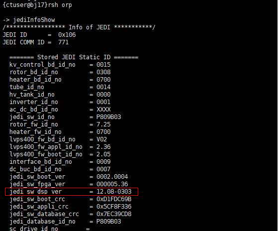
jediInfoShow
- JEDI info displays.
- If jedi_sw_dsp_ver is 12.**-****, the kV control board is SoC board.
- If jedi_sw_dsp_ver is not 12.**-****, for example: 10.**-**** or 11.**-****, the kV control board is PPC board.
Figure 1. Example for SoC Control Board
Or
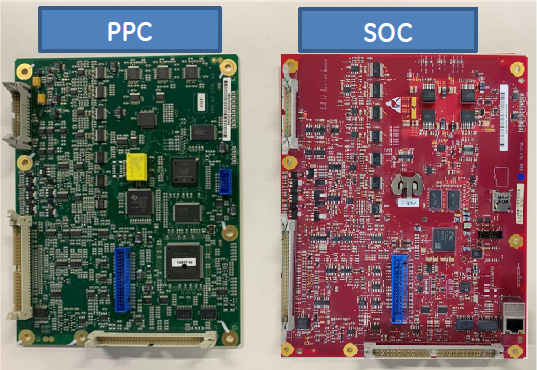
FE can also check kV control board PWA color to identify the board type, green color is PPC and deep red color is SoC.
Figure 2. kV Control Board
-
If possible, upload JEDI database (from JEDI to console)
-
Remove front cover of the Power Unit
-
Replace Programmed KV Control board
-
Replace the front cover
-
Reload JEDI software and appropriate database
1 Programmed KV Control Removal
Procedure
 danger
- Upload JEDI database (from JEDI) if you wish to retain the existing database after new KV control board installation. In most cases you will want to perform this step, however it may not be possible, depending on the failed KV control board. If it’s not possible, move on.
- Move table to its lowest elevation.
- Remove power to the gantry using proper Lockout/Tagout procedures.
- Remove side top and front gantry covers.
- Stop the rotor of X-ray tube in case of Liquid Bearing Tube before HVDC off. Refer to Liquid Bearing Tube Rotor stop procedure for details.
- Turn OFF all 3 switches (Axial Drive, HVDC, 120VAC) on the Service Switch Panel.
- Unscrew the 12 hex head screws, and remove the front cover from the Power Unit.
- Disconnect the 2 ribbon cables from the KV Control board.
- Disconnect all wire connections from the board.
- Unscrew the screws holding the KV Control board, and remove
the board.
Figure 3. Programmed KV Control Board
2 Programmed KV Control Installation
Procedure
- Install the new KV Control board.
- Re-connect all wires and ribbon cables.
- Re-install the front cover of the Power Unit.
- Download new software to the generator.
3 Finalization
Procedure
- Perform Gantry Rotation Safety Check.
- Perform Flash Download.note: If Flash Download failed, press dismiss button to exit Flash Download tool and execute the following procedure.
- Open unix shell with ctuser account and type the following.
/usr/g/GEfirm/ssInstall -jedi
- Confirm command prompt returns. And press “System reset” button from CSD home page, press “Scan” button and “run”.
- Confirm that the requested reset has successfully completed, and dismiss the tool.note: The following Error may happen after the command execution but ignore it, it’s not a problem.
Getting Database File stats for [/usr/g/ss_fw/jedi/sc_package.mx]
/usr/g/ss_fw/jedi/sc_package.mx: No such file or directory
Error getting stats on /usr/g/ss_fw/jedi/sc_package.mx.
- Open unix shell with ctuser account and type the following.
- Perform Gantry Balance Procedure.
- Perform Restore Runtime Parameters (Generator Tool).
- Perform Meter Verification.
- Perform HV Tank Feedback Resistor Verification .
- Perform Filament Calibration (Generator Tool).
- Perform HHS Scans.
- Perform System Scanning Test.
- Perform Quality Assurance Test.