- Topic ID: id_16158024
- Version: 4.0
- Date: Nov 27, 2020 2:16:56 AM
PDAS Backplane Board Replacement
Prerequisites
1 Low Channel Backplane Removal
Procedure
- notice
- Move the table cradle to the home position, and lower the table to its lowest elevation.
- Remove gantry right side cover.
- notice
- Turn OFF Axial Enable, HVDC, and 120VAC switches on the Service Switch panel.
- Remove the rest of the gantry covers.
- Position the PDAS at the 12 o'clock position.
- Lock the Gantry in position using the rotational lock.
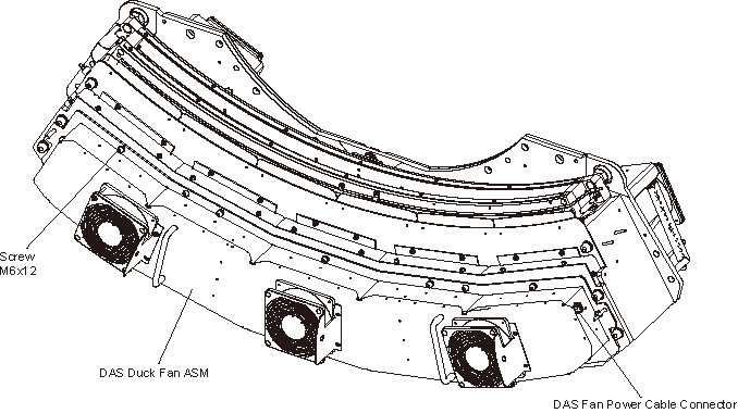
- Disconnect the fan power cable from the Duct Fan Cover.
- Remove the Duct Fan Cover by unscrewing its M6x12 allen screws
by a
 on the Duct Fan Cover.
Figure 1. Remove the Duct Fan ASM
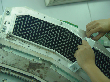
- Install two the cover handle (5488043) shipped with system ship
collector on the Air Filter ASM.
Figure 2. Install the Cover Handles
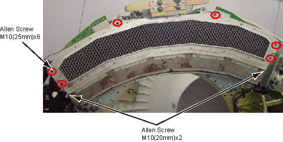
- Remove the Air Filter ASM and Detector Duct Fan Cover together
by unscrewing their M10x8 allen screws.
Figure 3. Remove Air Filter ASM and Detector Duct Fan Cover
- Put on Nitrile protective gloves and wrist strap and use ESD precautions.
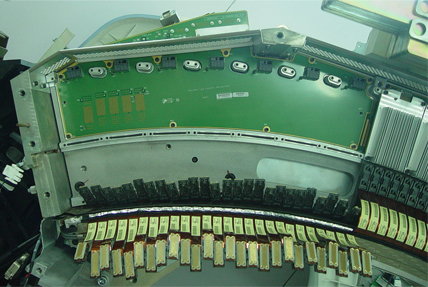
- Pull out the Flex Cable Leads from 7 ADBs of the Low Channel Backplane with the Flex Extraction Tool.
- Unscrew M4x6 screws for each ADB of the Low Channel Backplane.
- Remove ADBs from the Low Channel Backplane and place on an ESD
pad.
Figure 4. Remove ADBs from the Low Channel Backplane
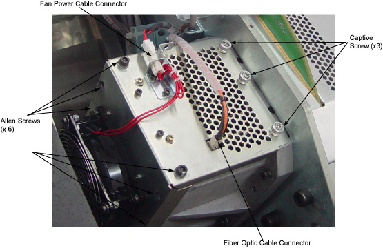
- Cut the tie-wrap holding the fiber optic cable to the IFB cover.
- Disconnect the fiber optic cable connector and the fan power cable connector.
- Remove M6 x 6 allen screws and loose the 3 captive screws on
the IFB cover.
Figure 5. Remove the IFB Cover
 note:
note:Do not unscrew any other screws on the IFB cover.
- Slide the IFB cover out of the IFB chassis.
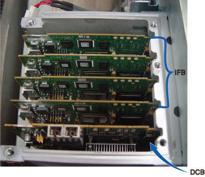
- Pull the IFBs and DCB out of the IFB chassis and place on an
ESD pad.
Figure 6. Remove IFBs
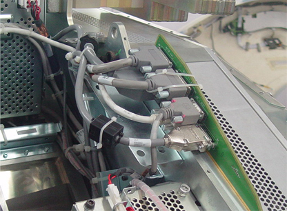
- Disconnect all cable connectors from back side of the backplane
board.
-
RCIB Out (J30)
-
RCIB In (J31)
-
JEDI (J32)
-
DHCB (J33)
-
Power (J51)
-
Signal (J41)
Figure 7. Disconnect All Cable Connectors from Backplane
-
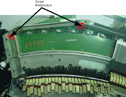
- Remove the right ADB enclosure cover by unscrewing its M4x4
screws.
Figure 8. Remove ADB Enclosure Cover
- Remove the Low Channel Backplane by unscrewing its M4x10 screws.
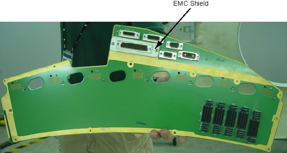
- Remove the EMC shield by unscrewing its 2 screws from the Backplane.
Figure 9. Remove the EMC Shield
- Place the defective Low Channel Backplane into an ESD bag.
 |
|
2 Low Channel Backplane Removal
Procedure
- notice
- Take out the new Low Channel Backplane from ESD bag.
- Install the EMC shield to the backplane.
- Secure the Low Channel Backplane by screwing M4(10mm)x10 screws. (Torque: 2.3N.m)
- Reinstall the right ADB enclosure cover by screwing M4(8mm)x4 screws. (Torque: 2.3N.m)
- Reconnect all cable connectors to the backplane.
- Reinsert the IFBs and DCB to the backplane.
- Reinstall the IFB cover to the IFB chassis by screwing M6x4 allen screws and 3 captive screws. (Torque: 7.9N.m)
- Reconnect the fiber optic cable connector and the fan power cable connector.
- Retie the tie-wrap to fix the fiber optic cable on the IFB cover.
- Align each ADB location hole to pin on backplane board and push it in place.
- notice
- Secure each ADB by using M4x6 screws. (Torque to 2.3N.m)
- Reconnect the Flex Cables to the ADBs.
Make sure the Flex Cable Leads are pushed perpendicularly in the DDIFs of the ADB.
- Reinstall the Air Filter ASM and Detector Duct Fan Cover by screwing 8 allen screws. (Torque: 38.4N.m)
- Uninstall two the cover handles from the Air Filter ASM..
- Reinstall the Duct Fan Cover by screwing its 12 allen screws. (Torque: 7.9N.m)
- Reconnect the fan power cable to the Duct Fan Cover.
- Disengage the rotational lock.
- Turn on Axial Enable, HVDC, and 120VAC switches on the Service Switch panel.
- Restore the Gantry to initial configuration.
|
|
3 High Channel Backplane Removal / Installation
Refer to Low Channel Backplane Removal / Installation for High Channel Backplane.
4 Finalization
Procedure
- DAS Detector Integration
- Perform X-Ray Verification.
- Perform Pop and Noise Microphonics Test (16-Slice).
- Perform FastCal.
- Perform “Image Quality Test Procedures” (located in folder).
- Perform Saving System State.
- Run 1 pass of DAS Tools.