- Topic ID: id_16157835
- Version: 2.0
- Date: Apr 9, 2020 8:42:16 PM
DAS-16 Interposer Replacement
Prerequisites
Overview
Reference MDAS/GDAS 16 DDIF Cleaning Procedure for detailed procedures.
1 Interposer Replacement Precautions
Procedure
- notice
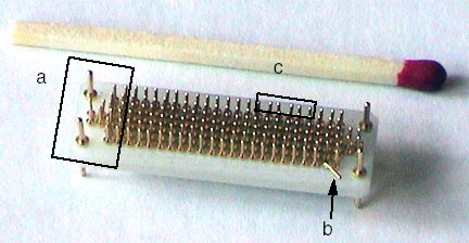
- Damage sustained by using wrong tool and rough handling.
- Bent pins - Result of screwdriver as a removal tool.
- Broken pin - Result of forcing the Flex onto the Interposer.
Also caused by using incorrect Interposer installation method.
- Loose pins - Result of forcing the Interposer to seat in the backplane BGA connector.
Figure 1. Interposer damaged by using wrong tools
 |
2 Broken Interposer Pin Removal
If you are reading this you are in desperate trouble. A male pin is broken off in a female socket. You have two choices;
Procedure
- Replace the DAS Chassis if pin is in the backplane BGA connector or replace the Detector if pin is in a flex lead.
- Attempt to remove the broken pin.note:
Do not break a pin off a good interposer so it will fit. Microphonics noise and/or image artifacts will result.
There is no specific procedure for this action. These are suggestions that may save you significant time and expense.
You will need a magnifying glass, ESD protection, Nitrile gloves and very sharp strong pointed tools.
-
Use ESD wrist strap and Nitrile gloves to prevent further damage to detector FETs or DAS electronics.
-
Move the table to its lowest position. Place the DAS near 6 O’clock and lock it in place. This will allow you to sit comfortably and use your knees as a resting place to keep your hands steady.
-
Use the magnifying glass to closely inspect the broken male pin. A small section should be visible since the female socket is cone shaped. Male pins generally break off at the base.
-
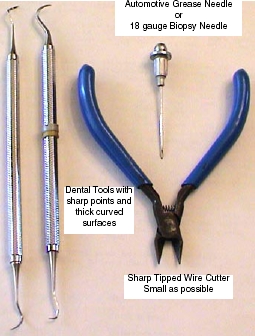
Use a biopsy needle, 18 gauge or larger, or a dental pick with a thick working surface. See Figure 2.
-
Biopsy needles can be found in most medical facilities.
-
Dental tools can be obtained from most Dentist offices. They regularly discard older utensils.
-
A grease needle can be purchased at an automotive parts store.
-
Objective:
Use the sharp pointed tool to raise the broken pin out of the female socket. Raise it enough so that a fine tipped wire cutter can extract the pin fully.
Warnings:
-
Be very careful not to damage the female connector. Deep scratches or gouges are bad and the component would need to be replaced.
-
Do not "Dig" the pin out. This will damage the female socket or connector.
-
Do not put anything in the female socket such as a needle.
-
Be careful of metal shavings. They can cause problems elsewhere.
-
Do not attempt to drill out a broken pin.
Testing:
-
Assemble gantry and restore power.
It takes 2 minutes of warm-up time for every minute the DAS was turned off, up to 1 hour.
-
Perform Image Quality testing.
Figure 2. Emergency Interposer Pin removal tools
-
3 Dust Shield Retainer Clip Replacement
Procedure
- notice
- Removal Procedure
This requires destroying the damaged Retainer Clip.
 warning
- Gantry covers are removed and Lockout/Tagout power control performed. See Accessing the MDAS Assembly.
- Failed retainer clip has been identified. Flex lead and Dust Shield have been removed.
- Remove flex lead and dust shield from left and right sides of
the failed retainer clip.
- Position Gantry with failed retainer clip at the 2 O’clock position.
- Lock the gantry in position, using the rotational lock.
Refer to “Rotational Locking Pin,” in Equipment Service - Gantry (located in the Safety tab of this publication).
- Using small sharp side cutters, grip the right side of the damaged
retainer clip. Squeeze the clip until it cracks and fragments into
smaller pieces.
Figure 3. Removing Retaining Clip from DDIF
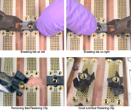
- Perform the same process as in the previous step on the left
side of the failed retainer clip.
You must destroy the damaged retainer clip to remove it.
- Remove from the backplane, all fragments of the destroyed retainer clip.
|
4 Installation Procedure
Procedure
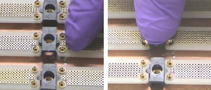
- Observe the new retainer clip has snap lock features on two sides. These snap locks secure to the "A" and "B" backplane BGA connectors.
- With your Nitrile Glove protected fingers, push the retainer
clip into place.
Make sure the new retainer clip is installed perpendicular to the backplane.
Figure 4. Positioning and Seating new Retaining Clip
- Assemble the DDIF, unlock the gantry.
- Restore gantry power.
It takes 2 minutes of warm-up time for every minute the DAS was turned off, up to 1 hour.
5 Finalization
Procedure
- Perform “Image Quality Test Procedures” (located in folder).