- Topic ID: id_16157836
- Version: 3.0
- Date: Nov 27, 2020 2:16:28 AM
DAS-16 Chassis and Backplane Replacement
Prerequisites
Overview
The DAS backplane is not a separate FRU; the entire chassis must be replaced. This procedure covers replacement of the left, center, and right chassis.
1 Chassis Removal (Left, Center or Right)
Procedure
- Move the table cradle to the home position, and lower the table to its lowest elevation.
- Remove gantry right side cover, and turn OFF all three (3) service switches. Remove the rest of the gantry covers.
 warning
- Position the bad chassis at 6 O’clock. Shut off system power using appropriate Lockout Tagout procedures.
- danger
- Lock the gantry in position, using the rotational lock.
Refer to “Rotational Locking Pin,” in Equipment Service - Gantry (located in the Safety tab of this publication).
- Remove the DAS air plenum, per DAS Air Plenum Removal and Installation.
- Put on wrist strap and use good ESD precautions.
- Using Detector Handling precautions (verify use of ESD strap, grounding and Nitrile gloves), disconnect Detector flexes from the appropriate backplane. See MDAS/GDAS 16 DDIF Cleaning Procedure for details.
- Disconnect the appropriate power cables:
- Disconnect the appropriate data cables:
- Remove the gantry balance trim weights and threaded rod nuts on the front of the detector plate. This is for left and right chassis replacement only.
- Loosen Center Chassis top mounting bolt for left or right chassis removal.
- Remove four (4) large 12mm cap screws holding the chassis to
the Detector Plate, while holding on to the chassis. When the last
cap screw is removed, carefully slide the chassis away from under
the Center chassis and remove from the Gantry. Place chassis on an
ESD pad (to protect converter cards).
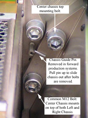
Figure 1. DAS Chassis mounting bolts, between right and center chassis
-
The center chassis shares one bolt each with the left and right chassis.
-
When removing the left or right chassis, the second bolt on the shared side of the center chassis must be loosened slightly.
-
Be careful not to damage detector flexes.
-
Use the DAS shields provided with the gantry balance kit to protect against particle contamination during balance weight removal and installation.
For systems with a GDAS, there may be a shield plate between the right DAS chassis and Jedi HV tank. See GDAS EMI Shielding for a description of this shield. This shield plate needs to be removed to remove the DAS right chassis and reinstalled when installing the new chassis.
2 Chassis Installation (Left, Center or Right)
Procedure
- notice
- Carefully place the DAS Chassis in position. Use special care:
-
Do not smash or otherwise damage Detector flexes
-
Ensure that ALL Detector flexes are in front of backplane
-
- Secure by using four (4) large 12mm Cap screws, with flat and
lock washers. Torque each chassis mounting screw to 49 ft.-lbs (66.4
N-m).
When replacing the left or right chassis, be sure to also tighten the center chassis screw that was loosened for removal.
- Connect the appropriate power cables:
- Connect Data Cables
- Transfer the Converter boards from the replaced chassis to the
new chassis.
- Confirm ESD practices
- Remove Chassis board cover
- Remove 1 board at a time and transfer each board from the original chassis to the new chassis in the same board slot location.
- Install Detector flexes with your Nitrile glove protected fingers.
- Confirm ESD and detector flex handling practices. Use ESD wrist strap and Nitrile gloves.
- Interposers and Dust Shields are shipped with each new chassis.
- Install chassis board cover.
If the right chassis was replaced, reattach the fiber-optic cable to the transmit (TX) port.
- Install threaded rod lock nuts, gantry balance trim weights and torque to 66 N-m (48 lbs-ft).
- Install plenum, per “Plenum Installation,” in DAS Air Plenum Removal and Installation.
- Return weights to their original sequence and position (if applicable).
- Disengage rotational lock.
- Restore power.
- See Retest Matrix for tests after replacing a DAS Chassis.
- Install / Close all covers.
3 Finalization
Procedure
- DAS Detector Integration
- Perform X-Ray Verification.
- Perform Pop and Noise Microphonics Test (16-Slice).
- Perform FastCal.
- Perform “Image Quality Test Procedures” (located in folder).
- Perform Saving System State.