- Topic ID: id_18718470
- Version: 1.0
- Date: Sep 20, 2018 2:02:28 PM
DARC2 Replacement
Prerequisites
Overview
This module describes the procedures used to replace the DARC2 Node in the GOC4 Console. After the DARC2 Node has been replaced and loaded with software, several tests are required:
-
Perform DARC OS software load from Host per LFC
-
Perform DARC Apps software load from Host per LFC
-
Communication and verification within the DARC2
-
Communication to the IG Node(s) and DARC2
-
Recon Data Path Diagnostic
-
Resave of the System State Reconfig Info
-
Sanity scans
Jarrell DARC2 and Jarrell IG Nodes require a software release of 06MW29.7 or greater.
1 Additional Software Supporting the DARC Node
2 Power-Off (Shut Down) the Operator Console
Procedure
- Select one of the following methods to Power OFF the Operator
Console:
- If Applications are up, click on the Shut Down button and select Shutdown.
- notice
- If Applications are down, open a Unix Shell at the Toolchest.
Type:
{ctuser@ hostname } halt

- The Operator Console monitor will display a 'System halted' message when it is acceptable to power OFF the Operator Console.
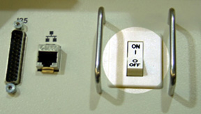
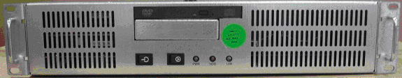
- Power OFF the Operator Console at the
front panel switch. See Figure 1.note:
Do not turn off the DARC2 Node Rear Power Switch (if present).
Figure 1. Power Switch
3 Remove the Old DARC-2 Node
Procedure
- Remove the front and rear Operator Console covers.
- Verify each cable label is present and clearly marked; if necessary, add a label for clarity.
- Disconnect all rear DARC2 Node cables.
- Remove and retain the four (4) front mounting screws and slide out the DARC2 Node.
4 Install the Replacement DARC2 Node
(For DARC2 part numbers 5114772-100 and 5147442-100 – DARC2 without DIP Boards: Install appropriate DIP board inside the DARC2 prior to install the DARC2 into the operator console. See DIP Board Replacement procedure for instructions on installing the DIP Board.) Exchange the DIP Board from the DARC2 being replaced or order a new DIP Board.
Procedure
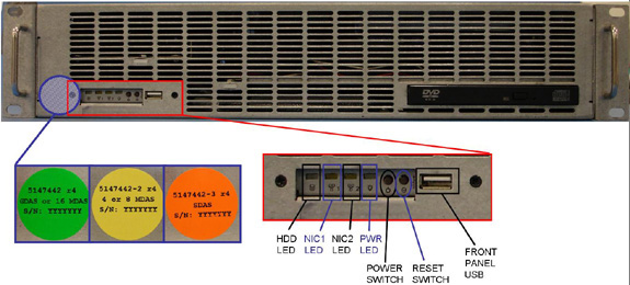
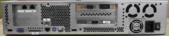
- Verify the replacement DARC2 Node is correct for the Site DAS
Type. Refer to the color-coded sticker located on the front panel
of the DARC2 Node for DIP type information.
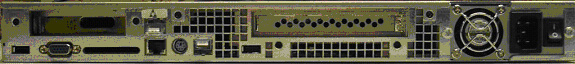
Figure 2. Jarrell DARC2 Node
Sheet 1 of 2
Sheet 2 of 2
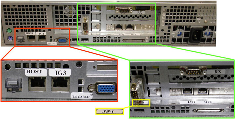
Figure 3. Westville DARC2 Node
Sheet 1 of 2
Sheet 2 of 2
- Slide the replacement DARC2 Node into the Operator Console from the front.
- Replace the four (4) front mounting screws on the front of the DARC2 Node.
- Reconnect the DARC2 Node cables, using Figure 2 and Figure 3 above as a guide. (Refer to the proper Illustration, depending on DARC2 Node version.)
- notice
- If present, verify the power switch located at the rear of the DARC2 Node is in the ON position.
|
5 Power-On the Console
Procedure
- Power ON the Operator Console at the front switch.
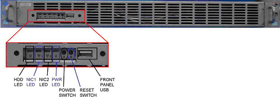
- At the DARC2 Node verify the front panel Power (PWR) LED is on. If not press the front panel power switch (hold 3-10 seconds) to apply power to the DARC2 Node.
- At each IG Node, verify the front panel Power (PWR) LED is on.
If not press the front panel power switch (hold 3-10 seconds) to apply
power to each IG Node. See Figure 4 or Figure 5, depending on IG Node version.
Figure 4. “Jarrell” IG Node
Sheet 1 of 2
Sheet 2 of 2
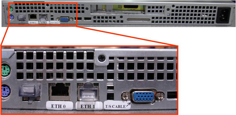
Figure 5. “Westville” IG Node
Sheet 1 of 2

Sheet 2 of 2
- Stop Applications from auto-starting at the 5 second PINK Box.
6 Verify DARC2 Node Is Ready for Software Load
The DARC2 Node must be up to load the OS (Operating System and DARC Application software. Perform the telnet command on the DARC2 Node to verify communication, as follows:
Procedure
- At the Toolchest, with Application software down, open a Unix Shell.
- Perform the telnet command to the DARC2 Node from the Host Computer:
{ctuser@ hostname } su -
Password: #bigguy
[root@ hostname ] service cliservice start
dpcproxy server will be reported as already running or restarted
[root@ hostname ] telnet localhost 623
Trying 127.0.0.1...
Connected to localhost.
*** Indicates cliservice proxy server is running ***
Escape character is '^]'.
Server: darc
Username: Enter
Password: Enter
Login successful << *** Indicates the SOL connection is established ***
dpccli> exit
Connection closed by foreign host.
[root@ hostname ]
note:If the telnet connection fails:
Load the SOL CD, if available, for current version of Software into the DARC2 Node and press the DARC Node reset switch (or re-power DARC2 Node if necessary). SOL CD will auto-eject when completed.
Verify the DARC2 Node is running on the Host Computer using the ifconfig command.
Verify the Ethernet cabling between the Host Computer (port C) and DARC2 Node.
7 Confirm Host PC Software
Confirm the Host Computer Software type. Examples are shown, the software version output should match the Software media to be loaded.
Procedure
- Open a Unix Shell.
- Type the following to verify software version information. Examples
are provided. The examples are not actual output.
-
{ctuser@
hostname
}
swhwinfo <<
for Apps version
(year) MW (fiscal week).(fiscal day).hardware revision info here
Example 1: 06MW03.4.V40_H_V64_G_GTL
Example 2 (supports Jarrell hardware): 06MW29.7.V40_H_V64_G_GTL
note:If the revisions do NOT match the software media to be loaded, locate the proper software set. If the software set cannot be found or ordered, a full LFC will be required for the Operator Console.
If the revisions match the software media to be loaded, continue with the load procedure
-
{ctuser@
hostname
}
swhwinfo –o << for OS version
Release: GEHC/CTT Linux 4.3.16
Built: Tue Jul 12 12:29:10 CTD 2005
note:Confirm that the results match the Operating System version and Software Build Date shown on the OS and Applications DVDs.
-
{ctuser@
hostname
}
swhwinfo <<
for Apps version
8 Load Software from Host onto DARC2 Node
The DARC2 Node must be loaded with the OS and Application software from the Host Computer to the DARC2 Node. Set-up the DARC2 Node Boot Order BIOS to allow the software to load from the Host Computer. Perform the DARC2 Node OS (Operating System) load as described in the LFC (load From Cold) procedure for the software set being used. Perform the DARC2 Node Application software load as described in the LFC (Load From Cold) procedure for the software set being used. Return the DARC2 Node Boot Order BIOS (reset to original configuration) to avoid problems with the DARC2 Node Motherboard bootup. Refer to the appropriate LFC procedure and follow the sub-sections after reading the DARC Subnet information outlined below:
Procedure
- Perform the DARC2 Node OS (Operating System) load as described
in the LFC (Load From Cold) procedure for the software set being used.note:
If the OS software fails to load successfully on the DARC2 Node from the Host Computer.
-
Check the DARC Node Boot Order BIOS
-
Refer to the “LFC - DVD OS Installation on DARC” section of the appropriate LFC Procedure
-
- Perform a DARC2 Applications software load (as described in
the LFC procedure for the software set being used) on the DARC2 Node
from the Host Computer per the normal instructions. Refer to the DARC
Subnet Note below.note:
DARC Subnet Address Information: The following procedure should be performed if your customer Ethernet hospital backbone begins with 172.16.0.xx, OR if the scanner will connect to a device with an IP address of 172.16.0.xx.
-
If the hospital backbone starts with 172.16.0.xx, and the DARC subnet was previously set to 169.254.0. during the LFC procedure on this Operating Console, verify that the Change DARC subnet? box is checked during the Application software load and the DARC subnet address is set at 169.254.0
-
If the DARC subnet was previously set to 169.254.0. and needs to be set back to the 172.16.0 subnet, uncheck the Change DARC subnet? box during the Application software load
-
- Perform the DARC2 Node Boot Order BIOS (reset back to original configuration) as described in the LFC (Load From Cold) procedure for the software set being used.
The OS (Operating System) and Application software version loaded onto the DARC2 Node must match the OS and Application software versions loaded on the Host Computer.
9 Verify Replacement DARC2 Node
With Application Software Down, the DARC2 Node must be checked to verify communication between the Host Computer and the DARC2 Node. Perform ping and rsh commands on the DARC2 Node, as follows:
Procedure
-
Host Computer (xw8000 or xw8200) example Ethernet cable check:
[root@ hostname ] ethtool –p eth2
(Ctrl+C to stop flashing xw8000 Ethernet port C LED)
[root@ hostname ] ethtool –p eth0
(Ctrl+C to stop flashing xw8200 Ethernet port C LED)
-
Remote Shell to the DARC2 Node:
[root@hostname] rsh darc
-
DARC2 Node (Jarrell and Westville) example Ethernet cable check:
[root@darc] ethtool –p eth2
(Ctrl+C to stop flashing DARC2 Node Ethernet port LED)
- At the Toolchest, with Application software down, open a Unix Shell.
- Ping the DARC2 Node:
{ctuser@ hostname } ping darc
Verify ping is successful.
Output similar to the following will appear:
PING darc (172.16.0.2) from 172.16.0.1 : 56(84) bytes of data. 64 bytes from darc (172.16.0.2): icmp_seq=1 ttl=64 time=0.157 ms
Press Ctrl+C to stop ping process.
Output similar to the following will appear:
--- darc ping statistics ---
4 packets transmitted, 4 received, 0% loss, time 3000ms
rtt min/avg/max/mdev = 0.134/0.168/0.209/0.031 ms
- Remote Shell to the DARC2 Node:
{ctuser@ hostname } rsh darc
Last login: Thu Oct 9 11:17:35 on ttyS1
{ctuser@darc}
Verify ctuser@darc prompt is present.
- Verify the DARC2 Node DIP board type (see table, below).
{ctuser@darc} cat /proc/driver/dip
- Verify the DARC2 Node DAS Interface Processor Board (DIP) Diagnostics
pass.
{ctuser@darc} DipDiag -x 1,2,3,4,5,6
note:Because tests 7 and 8 require the installation of a loopback cable, they are not being performed.
12:05:40 opening LINUX device /dev/dip
creating H16 dip interface
note:IGNORE the H16 reference in the previous line.
DIP PN : Part Number Board Version Letter
note:An example of the DAS Interface Processor Board (DIP) is provided. The specific DIP Board & Revision information will be identified for the DARC2 Node type.
test 1 Passed X-ray Enable Relay
test 2 Passed Test FEC Bit
test 3 Passed Test EDDR Bit
test 4 Passed Test Magic Number Register
fill mem
write to dip took 4.714 sec
verifying memory
read from dip took 19.469 sec
test 5 Passed Memory Test
test 6 Passed Interrupt Test
1 loops 0 failures
note:The Unix Shell will be used again, so do not exit or close at this time.
For a Ethernet cabling connection issues, use the ethtool command (ethtool –p eth# where # represents the Ethernet address) as root on the Host Computer, DARC2 Node or IG Node to determine if the Ethernet cable is correctly connected. The port will blink or flash when activated and Ctrl+C will stop the test. This command must be performed as root.
Open a Unix Shell and type the following
If the DARC login prompt [root@darc] is not present, then the Application software load has not been successful. If the DARC login prompt [root@localhost root] is present, then reloading the DARC Node OS again per the procedure. If ping darc command fails perform an ifconfig on the Host and verify the DARC is RUNNING and the address is correct. Check the Ethernet cable. Re-power the Operator Console, after a halt, as required to troubleshoot.
10 Re-Power the IG Node(s)
Remove the power for each IG Node, then re-power each IG Node with the DARC2 Node up and able to Remote Shell (rsh darc).
Procedure
- At each IG Node, verify the power is OFF. If power is On for any IG Node, then press the front panel power switch (hold 3-10 seconds) to remove power to each IG Node present in the Operator Console.
- Wait 20 seconds.
- At each IG Node, press the front panel power switch (hold 3-10 seconds) to apply power to the IG Node(s).
- Wait 2 minutes for each IG Node present in the Operator Console to boot up.
11 Verify Communication from DARC2 Node to IG Nodes
The DARC2 Node must be up to check the IG Node(s). Perform ping and rsh commands on the DARC2 Node, as follows:
Procedure
-
IG1
[root@darc] ethtool –p eth1
(Ctrl+C to stop flashing Ethernet port LED)
[root@ig1] ethtool –p eth0
(Ctrl+C to stop flashing Ethernet port LED)
-
IG2 (Upgrade Option on some Operator Console Types)
[root@darc] ethtool –p eth0
(Ctrl+C to stop flashing Ethernet port LED)
[root@ig2] ethtool –p eth0
(Ctrl+C to stop flashing Ethernet port LED)
-
IG3 (Upgrade Option on some Operator Console Types)
[root@darc] ethtool –p eth3
(Ctrl+C to stop flashing Ethernet port LED)
[root@ig3] ethtool –p eth0
(Ctrl+C to stop flashing Ethernet port LED)
- At the Toolchest, with Application software down, if necessary, open a Unix Shell.
- Ping IG Node #1:
{ctuser@darc} ping ig1
Verify ping is successful.
Press Ctrl+C to stop ping process.
- Remote Shell to the IG Node #1:
{ctuser@darc} rsh ig1
Verify ctuser@ig1 prompt is present.
- Exit from the IG Node #1 Remote Shell:
{ctuser@ig1} exit
- Ping IG Node #2:
{ctuser@darc} ping ig2
Verify ping is successful.
Press Ctrl+C to stop ping process.
- Remote Shell to the IG Node #2:
{ctuser@darc} rsh ig2
Verify ctuser@ig2 prompt is present.
- Exit from the IG Node #2 Remote Shell:
{ctuser@ig2} exit
- Ping IG Node #3:
{ctuser@darc} ping ig3
Verify ping is successful.
Press Ctrl+C to stop ping process.
- Remote Shell to the IG Node #3:
{ctuser@darc} rsh ig3
Verify ctuser@ig3 prompt is present.
- Exit from the IG Node #3 Remote Shell:
{ctuser@ig3} exit
- Exit from the DARC Node Remote Shell:
{ctuser@darc} exit
{ctuser@ hostname }
For a Ethernet cabling connection issues, use the ethtool command (ethtool –p eth# where # represents the Ethernet address) as root on the Host Computer, DARC2 Node or IG Node to determine if the Ethernet cable is correctly connected. The port will blink or flash when activated and Ctrl-C will stop the test. This command must be performed as root.
12 Verify the DARC2 Node Internal Disk Array
In the following test, the Disk Array is configured with 2 disks (internal to the DARC2 Node). Visually verify the entire output is successful from the command script performed. The final output line ‘gre-raid success’ does not mean the 2 Disk Array is good.
Procedure
- Type the following:
{ctuser@ hostname } rsh darc
{ctuser@darc} sudo gre-raid -z -c
answer: yes
- Verify the create partitions diagnostic passes and all output
looks good.
{ctuser@darc} sudo gre-raid -a
- Verify assemble diagnostic passes and all output looks good.
{ctuser@darc} sudo gre-raid -q
- Verify query diagnostic passes and all output looks good.
{ctuser@darc} exit
{ctuser@ hostname }
note:The Unix Shell will be used again, so do not exit or close at this time.
This procedure is applicable only to 06MW03.x software or newer. For older versions of software, perform the following:
Application Software must be down.
13 Verify the IG Node RAC
In the following test, the Image Generator Node(s) RAC (Recon Accelerator Card) will be tested.
Procedure
-
{ctuser@
hostname
}
racdiags
note:
The command racdiags will test up to three (3) IG Node RAC’s. If only one (1) IG Node is present in the Operator Console ignore any errors associated with IG2 or IG3. To test a single IG Node perform the following command:
{ctuser@ hostname } racdiags 1
- Verify rac diagnostic passes for each IG Node configured in
the Operator Console.note:
The Unix Shell will be used again, so do not exit or close at this time.
Application Software must be down.
14 Start Up Application Software
{ctuser@ hostname } st
15 Retro Recon Test
The Reconstruction (not Scan) portion of the system can be tested at this point.
Procedure
- Verify the FSA Box is Idle (not Paused). If paused, click on Recon Management and Restart the Queue.
- Select RETRO RECON on the left Monitor.
- Select RAT GOLD series.
- Select SELECT SERIES.
- Select CONFIRM.
- Verify the image(s) reconstruct and are displayed.
- Select QUIT.
16 Verify Recon Data Path Diagnostic
Procedure
- Select the Service Icon.
- Select DIAGNOSTICS.
- Select Recon Data Path.
- Select 1 and ALL
- Select RUN
- Verify Recon Data Path tests pass.
- Select Dismiss.
17 Re-Save Reconfig Info File on System State
After the DARC Node software load (OS and Apps), the Reconfig Info file must be re-saved on the System State DVD-RAM.
Procedure
- Insert the System State DVD-RAM into the SCSI Tower DVD RAM drive.
- Wait until the DVD drive is ready (i.e., until the front panel green LED is no longer lit).
- Select: Service icon to access the CSD (Common Service Desktop).
- Select: Utilities.
- Select: System State.
Figure 6. System State GUI
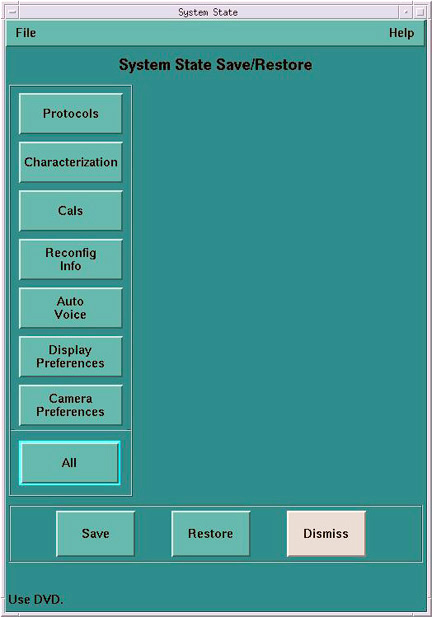
- Select Reconfig Info.
- Select Save.
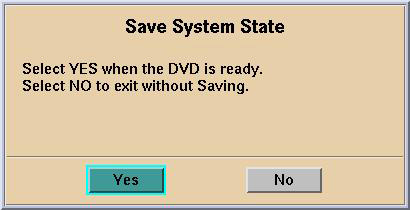
- If applicable, select Yes when the following
message appears: System State Media Status: Please insert
a DVD into the drive and press Save again.
Figure 7. Save System State Ready
 note:
note:Verify that the "Save" of System State was successful. If not, correct any errors and re-save the Reconfig Info file on the System State DVD-RAM. A message at the end of the Save should state: Save/Restore System State: Completed Successfully.
- When completed, select CANCEL.
- notice
- When completed, select Dismiss.
- Close the Service Desktop window at the upper left corner of the screen
|
18 Finalization
Procedure
- Perform sanity scans (e.g., scout, axial and helical).note:
If the System will not scan or reconstruct verify the memory on the DARC2 Node is correct (lhinv). Verify the DIP diagnostics pass Verify the RAC diagnostics pass.
- Verify the image(s) reconstruct and are displayed.
- Install the front and rear Operator Console covers.