- Topic ID: id_16157831
- Version: 2.0
- Date: Apr 9, 2020 8:48:55 PM
Axial Drive Motor Assembly Replacement
Prerequisites
Overview
Procedure
- Remove gantry covers as required.
Refer to
- Remove the Lower slipring cover.
- Remove the tilting gantry bottom cover.
 danger
- Turn off all 3 switches (Axial Drive, HVDC, 120VAC). Remove all system power at the Main Disconnect panel and use proper Lockout/Tagout procedures.
- Rotate the tube to the 3:00 position.
- Disconnect the Control and Dynamic Brake cabling at the Axial
Drive Module.
Refer to Axial Drive Module Replacement, for details.
- Remove the Drive Gear cover.
- Using a 6mm hex key, or hex bit socket, and a 12 inch extension,
fully loosen the elongated hex screw to loosen the drive belt.
Figure 1. To loosen drive belt, loosen 2 screws and the long hex screw
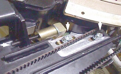
- Remove the drive belt from the drive gear. Take care to not disturb the teeth engagement along the rotating assembly.
- Using a 10mm hex key, or hex bit socket, loosen two (2) screws that will loosen drive belt.
- warning
- Assemble hoist and use it to support the motor.
- warning
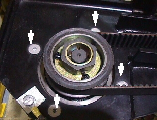
- Loosen four (4) hex screws, using a hex bit socket, to release
motor and remove ground cable.
Figure 2. Removing the four (4) hex screws will release motor
- caution
- Replace motor and secure it in place. If the 6mm bolts that
were removed have Loctite on them, clean the bolts and reapply Loctite
242. For all others, set the torque on the four hex bolts to the following
value.
- Install the drive belt on the drive gear and tension belt.
For details, refer to Belt Removal and Installation.
- Connect cabling to Axial Drive module. Reference Axial Drive Module Replacement.
- Reassemble gantry.
 |
Finalization
- Perform Axial Control Functional, located in Axial Motion Checks.
- Perform System Scanning Test (located in folder).