- Topic ID: id_2025002
- Version: 3.0
- Date: Nov 27, 2020 2:19:37 AM
Equipment Service - Lockout Tagout (LOTO) Overview
Overview of all Lockout Tagout scenarios.
Refer to the below tables for information on the basic knowledge of LOTO for the CT system. The sections below have more detail on subsystem items and LOTO overview.
Follow these general rules:
- All installed GE Healthcare systems require a LOTO compatible Main Disconnect to lock out power going to the GE system PDU.
- Only qualified service personnel trained in the service and operation of this scanner, options, and accessories should perform any service on this equipment. Service personnel must observe and apply LOTO as defined by annual LOTO training.
- Person Protection Equipment (PPE) PPE is required and must be worn and used when performing service on this equipment. Always use PPE when working with hazardous chemicals or materials.
The service switches and circuit breakers described hereafter are not to be relied on as personal protection devices. They do not replace lockout and tag out of main power to ensure personal safety. Switches and breakers are intended to only inhibit particular system functions and equipment operation during troubleshooting. They do not eliminate or remove the electrical or mechanical hazards that exist. Because hardware can fail and defeat the functionality of these devices, only Lockout/Tagout ensures protection from energy sources.
Here are the subsystems of the scanner and their energy sources with the location/definition.
2 Scanner Desktop
Electrical: The Scanner Desktop is powered by 208 V AC (2 Phase) electrical source coming from the System PDU. The primary lock out method is full system power down with the lock out at the A1/Main Disconnect Panel. Refer to LOTO - Electrical - System Power Off
Thermal: Though the potential exists where temperatures of components in the Scanner Desktop may exceed safe threshold for personal handling (ex: short circuit failure), generally temperatures should not exceed 50 degrees C / 122 degrees F (worse case condition). Before handling any components in the Scanner Desktop, allow a few minutes to pass after power off condition has been confirmed.
3 System Cabinet
Electrical: The System Cabinet is powered by 208 V AC (3 Phase) electrical source coming from the System PDU. The primary lock out method is full system power down with the lock out at the A1/Main Disconnect Panel. Refer to LOTO - Electrical - System Power Off.
Thermal: Though the potential exists where temperatures of components in the System Cabinet may exceed safe threshold for personal handling (example: short circuit failure), generally temperatures should not exceed 50 degrees C / 122 degrees F (worse case condition). Before handling any components in the System Cabinet, allow a few minutes to pass after power off condition has been confirmed.
4 Gantry
Electrical: The electrical power for the gantry is a direct feed from the PDU to the gantry power pan. The connection at the gantry are the large round power plugs at the rear base of the gantry behind the base covers. The primary lock out method is full system power down with the lock out at the A1/Main Disconnect Panel. Refer to LOTO - Electrical - System Power Off.
Mechanical: When the system is powered up, the axial drive controls the rotating assembly. However, when the gantry is powered off, the rotating assembly is free to rotate. The rotating assembly is a tightly balanced set of components. Removal of any item will cause the rotating assembly to suddenly want to turn. To prevent this from happening, engage the Rotational Service Lock located on the front left or right side of the gantry. These locks slide into predefined positions and have a safety cover that allows the latch to be locked out using the LOTO lock. Refer to LOTO - Mechanical - Gantry .
Thermal: There are numerous components on the gantry that can become hot during operation: tube, inverter, and axial brake assembly. Care must be taken to pay attention to the hot surface warning labels and waiting the appropriate length of time defined by the service procedures prior to accessing and servicing the component.
5 PDU
Electrical: The PDU is the electrical power distribution for the system. The power comes from the A1/Main Disconnect Panel and is hard wired to terminal connectors inside the PDU. There are no “plug” connections to or from the PDU. Due to this the only Lock out location is the A1/Main Disconnect Panel. Refer to LOTO - Electrical - System Power Off.
Stored Energy: The PDU has large capacitors that do store energy for a brief period after power is shut down. Care must be taken to wait for that power to dissipate after power is removed from the system. Refer to LOTO - Electrical - System Power Off.
6 Table
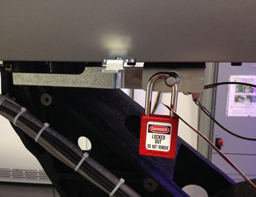
Electrical: The table electrical energy comes from the system PDU through the Gantry power pan. Power is the form of 120VAC and 24V DC is routed through connectors at the front base of the table. The only location available for locking out power to the table is the system A1/Main Disconnect panel. Refer to LOTO - Mechanical and Electrical - Table and LOTO - Electrical - System Power Off.
Figure 1. Table LOTO Lock Position