Wear proper electrical PPE. Perform proper electrical Lockout-Tagout (LOTO). Wait five minutes after applying electrical LOTO before using a meter to measure voltage or service the equipment.
warning
Biological Hazard
Bodily fluids, sharps, and medical waste from patients are present. Do not place hands or fingers under the gantry, base of the table, or foot pedal assembly.
Follow all of your organization’s bloodborne pathogen procedures and policies as well as any local policies, laws, and regulations.
notice
PPE Required
Follow ALL required safety and PPE procedures customary for your organization when working on this product.
Follow these general rules:
All installed GE Healthcare systems require a LOTO compatible Main Disconnect to lock out power going to the GE system PDU.
Only qualified service personnel trained in the service and operation of this scanner, options, and accessories should perform any service on this equipment. Service personnel must observe and apply LOTO as defined by annual LOTO training.
Equipment fuses, switches, and circuit breakers are for fire and equipment protection only. Do not rely on them to protect you against electrical shock or un-commanded equipment motion. This includes the Gantry Service Switch Panel!
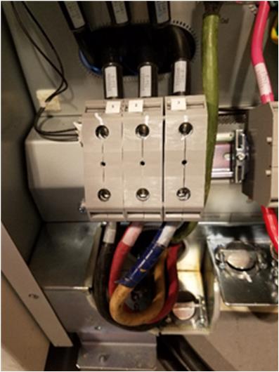
1 A1/Main Disconnect panel LOTO
The A1/Main Disconnect Panel is the location to lock and tag a system for full electrical isolation.
note: When the A1 panel is shutdown manually (LOTO) the UPS is also shut down automatically.
Prepare for shutdown of equipment. Notify affected personnel working in the area, via verbal communication, that LOTO is being performed.
Bring the system software down at the Scanner Desktop. Refer to System Shutdown Procedure in System Shutdown and Restart.
On the gantry service panel, turn OFF the HVDC, X-Ray Enable, Axial Motion Enable, and 120VAC service switches.
At the front of the PDU, turn OFF the PDU by pressing the Gantry Enable button (GREEN light should turn off).
After software shutdown is complete, press the emergency stop button on the A1 Panel or Main Disconnect Panel.
If there is an on/off switch controlled by a key, turn it to the OFF position.
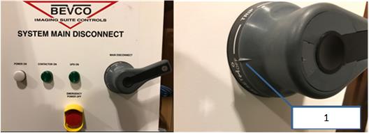
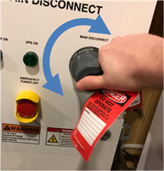
Ensure the handle is all the way into the OFF position. This is indicated by the handle position indicator pointing to the OFF text.
Figure 1. Main Disconnect panel showing proper OFF position
Callout
Description
1
Handle position indicator
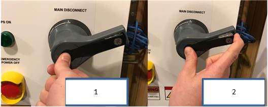
Once the handle is in the OFF position, press the center of the handle and lift out the back of the handle, exposing the holes for the installation of LOTO locks.
Figure 2.
Callout
Description
1
Press center of handle
2
Lift out LOTO bar from handle
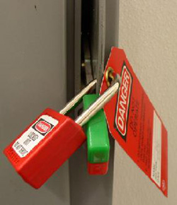
Ensure that each person servicing the system places their personal LOTO devices and tags on the A1 Panel of Main Disconnect Panel.
Figure 3. A1/Main Disconnect panel example
Once the LOTO lock is applied, attempt to rotate handle to ensure the handle will not turn the panel on, as shown in the figure below. If the handle is able to rotate such that the panel could turn on, rotate as far as possible in a counter-clockwise direction and try turning the handle back on again.
Figure 4. Attempt to rotate the handle after the LOTO lock is applied to ensure the handle will not rotate and turn the panel on.
Wait five minutes for any stored energy in capacitors to dissipate.
Verify that all energy has been dissipated.
danger
Electrocution (Stored Energy) Hazard
Risk of Severe Personal Injury or Death
Wear proper electrical PPE. Perform proper electrical Lockout-Tagout (LOTO). Wait five minutes after applying electrical LOTO before using a meter to measure voltage or service the equipment.
Measure incoming system power at TS1 (for NGPDU). With your PPE (Category 2) on, confirm power is off by checking power with your multi-meter at Terminal 1 on the PDU.
Figure 5. Terminal 1 location
Measure each phase to ground with a digital voltmeter (DVM) and verify electrical power is not present.
Perform service to the CT system according to service instructions.

 danger