
- SIGNA™ Hero 3.0T Service Methods
- 5852800-8EN Revision 1.0
- 00000018WIA30C4A230GYZ
- id_156674991.3
- Jul 13, 2021 4:27:36 PM
Wiring Modification of Control Box and TCU Replacement
Prerequisites
| Required persons | Preliminary requirements | Procedure | Finalization |
|---|---|---|---|
| 1 | Not Applicable | 30 minutes | Not Applicable |
| Item | Quantity | Effectivity | Part number | Manufacturer |
|---|---|---|---|---|
| Standard Tool | 1 | - | - | - |
| TORX driver | 1 | - | - | - |
| Plastic Tape (0.75 inch (19mm) or so) | 1 | - | - | - |
| Equipment for LOTO | 1 | - | - | - |
| PPE | 1 | - | - | - |
| DVM | 1 | - | - | - |
| ||||
Procedure
- Open ICC Cover and remove it by removing the lock at the upper
hinge location.
Figure 1. Remove ICC Cover 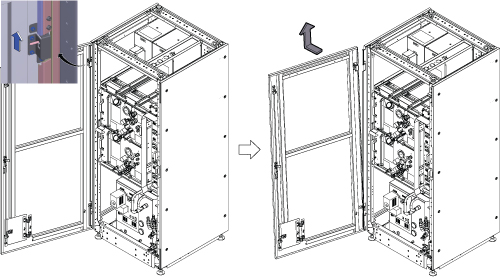
- Prepare DVM and wrap the plastic tape on the red probe lead
insulating all metal except for the very tip.Note:
This is for avoiding a short when measuring at a pin of D-Sub connector.
Figure 2. Wrapping tape on the lead 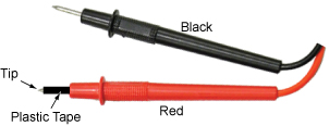
- Turn OFF the following sub breakers at ISC PDU.
- RF Amp OFF.
- Gradient OFF.
Figure 3. Turn OFF sub breakers 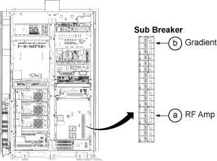
- While ISC power is on, perform the following functional check.
- Power on 3Q1(CCU Switch) and 3Q2(GCU Switch).
Figure 4. Functional Check 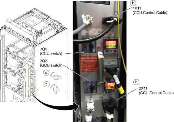
- Measure the DC voltage for Pin 17 on cable 1X11 and ground (See
illustration below), and write down the value in the table below.
(It should be 15.0 VDC ~ 24.0 VDC) (←Case1 (Normal
case))Note:
If there is no voltage at Pin 17(this is very rare case), check the voltage at Pin18 and write down the voltage in table below with comment for Pin 18. In this case, wiring modification will be different from normal case. (←Case2 (rare case))
Cable 1X11 Pin 17 Voltage (V) Comment Figure 5. DV voltage for Pin 17 on cable 1X11 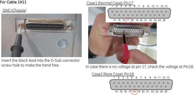
- Measure the DC voltage for Pin 18 on cable 2X11 and ground,
and write down the value in the table below. (It should be 15.0 VDC
~ 24.0 VDC) (←Case1 (Normal Case))Note:
If there is no voltage at Pin 18(this is very rare case), check the voltage at Pin19 and write down the voltage in table below with comment for Pin 19. In this case, wiring modification will be different from normal case. (←Case2 (Rare case))
Cable 2X11 Pin 18 Voltage (V) Comment Figure 6. DC voltage for Pin 18 on cable 2X11 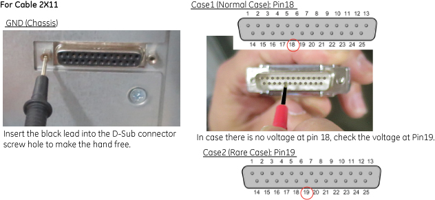
- Power on 3Q1(CCU Switch) and 3Q2(GCU Switch).
- Confirm that there is no voltage at the J1 terminal of control
box.
Figure 7. J1 terminal at Control Box 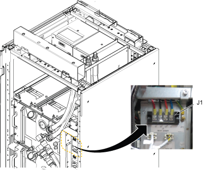
- Disconnect all cables from Control Unit. See illustration below.
Figure 8. Cables at Control Box 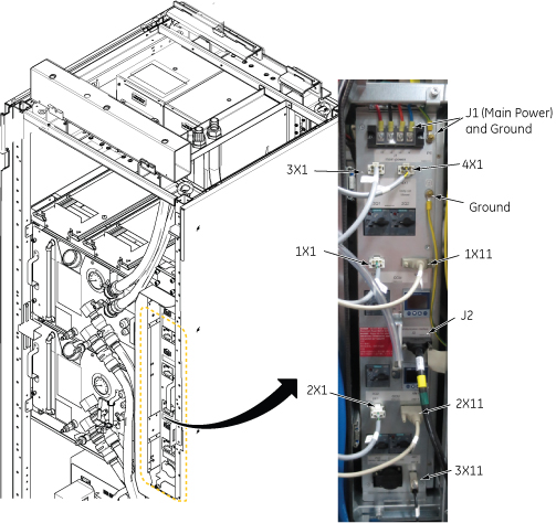
- Loosen two screws and carefully withdraw Control Unit from the
chassis.
Figure 9. Withdraw Control Unit 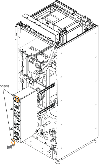
- Remove side cover of control box by loosening screws per the
following Illustration.
Figure 10. Remove side cover of control box 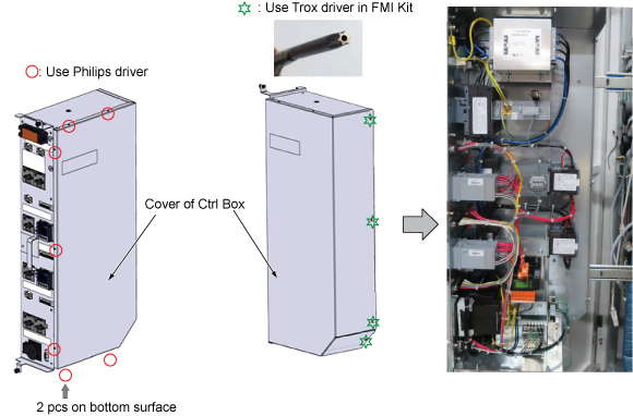
- For the Case1 (normal case) in step 5.d and step 5.e, change
the wiring for both TCU terminals per following steps.
- Move a cable from X1:3 to X1:2.
Figure 11. Wiring modification for Case1 (Normal case) 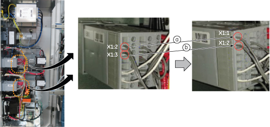 Note:
Note:For Case2 (Rare Case) in step 5.d and step5.e, move a cable from X1:3 to X1:1 only (c).
Figure 12. Wiring modification for Case2 (rare case) 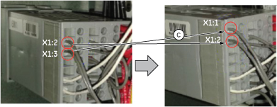
How to disconnect and connect the cable: Use the small flathead screw driver and do as follows.
Figure 13. How to disconnect and connect the cable 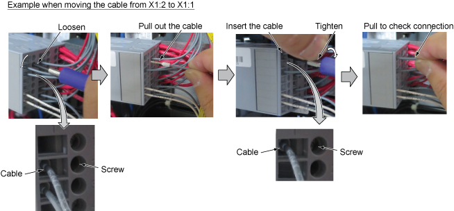
- Move a cable from X1:3 to X1:2.
- Replace TCU as follows.
-
CCU TCU: 5723568 -> 5723568-3 (Part number can be identified by package of this Assy.)
-
GCU TCU: 5723568-2 -> 5723568-4 (Part number can be identified by package of this Assy.)
When removing the TCU, push both top and bottom of TCU grip and pull out.
When inserting the TCU, make sure that the latches (below knurled area) snap into place.
Figure 14. Remove TCU 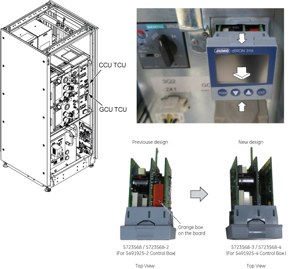
-
- Write down the following information on the small piece of paper
and attach on Control box as shown below. [5491925-3 Equivalent]
Figure 15. Label 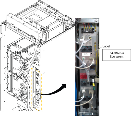
- Confirm that TCU indicator “5” is shown(lit) and
pressure meter indicates proper value for CCU and GCU.
Figure 16. Operation check 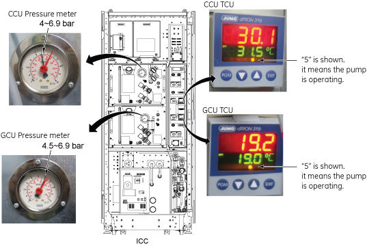
Finalization
No finalization steps.