- SIGNA™ Hero 3.0T Service Methods
- 5852800-8EN Revision 1.0
- 00000018WIA30DF8110GYZ
- id_20042165.0
- Apr 24, 2019 6:20:39 AM
Setting up 3.0T HD shoulder array
Use this procedure to set up the three-channel (3ch) shoulder coil for the Multi-Coil Quality Assurance (MCQA) check.
Prerequisites
| Personnel requirements | |||
|---|---|---|---|
| Required persons | Preliminary requirements | Procedure | Finalization |
| 1 | - | 15 minutes | - |
| Tools and test equipment | |||
|---|---|---|---|
| Item | Quantity | Part number | Manufacturer |
| Phantom Positioner | 1 | 2375136-3 | - |
| Head TLT Sphere for 3.0T (Pink Solution) | 1 | 2359877 | - |
| Safety |
|---|
|
Before working in any GE Healthcare MR suite or performing any GE Healthcare service procedure, you must:
If you have any safety concerns at any time, do not begin work or immediately stop work and move to a safe location. Immediately contact your supervisor or site safety officer for instructions on how to proceed. |
Procedure
- Insert the flat filler panel into the magnet end of the table.
Figure 1. Flat filler panel 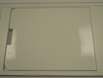
- Place the coil on the phantom positioner and connect the coil cable to port P2.Note: If the phantom positioner is newly ordered as FRU, remove the extra parts at the bottom so the bottom plate lays flat.
Figure 2. Remove bottom parts 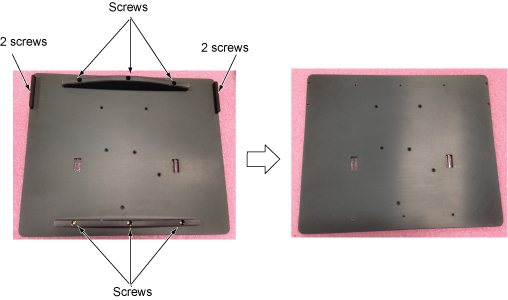 If applicable, assemble the phantom positioner using the following steps:
- Assemble the two tall large diameter posts (with small diameter posts on top) to the phantom positioning plate using the brass screws provided. The two tall large diameter posts will fit into the two large diameter pockets at the head end of the plate.
- Assemble the three small diameter posts (with angled top) to the phantom positioning plate using the brass screws provided. These three posts have the mounting holes offset from the center of the rod so they can only be assembled in the three holes in the plate that have the corresponding offset mounting holes.
- Assemble the short large diameter post (with small diameter posts on top) to the phantom positioning plate using the brass screws provided. The short large diameter post fits into the remaining pockets in the center of the positioning plate.
Figure 3. Assemble the phantom positioner 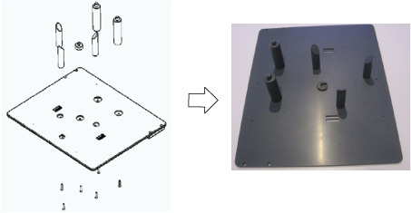
- Insert the phantom into the coil, then guide the coil onto the phantom positioner pins. The holes in the coil frame will accept the positioner pins.
Figure 4. Phantom positioner, coil, and cable connection on flat table 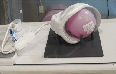
- Landmark on the coil crosshairs.
Figure 5. Landmarking on coil 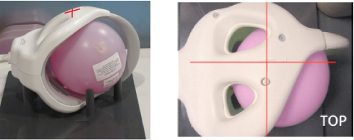
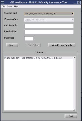
- Run the MCQA check.Note: Select 3.0T_HD_Shoulder_Array_by_GE in the Current Coil field.
Figure 6. MCQA tool menu