Removes the front cover from the magnet.
Prerequisites
Table 1. Personnel requirements| Personnel requirements |
|---|
| Required persons | Preliminary requirements | Procedure | Finalization |
|---|
| 2 | 60 minutes | 15 minutes | - |
| Tools and test equipment |
|---|
| Item | Quantity | Part number | Manufacturer |
|---|
| Nonmagnetic Titanium Service Tool Kit, Small Set | 1 | 5113258 | - |
| Required conditions |
|---|
| Front endbell is removed |
| Left and right control panel covers are removed |
| Left-hand upper front cover is removed |
| Rear cable cover is removed |
| Rear bridge inner cover is removed |
| Right-hand center cover is removed |
| Patient table is removed |
Procedure
- If installed, disconnect cable connectors from alignment laser, Operator Control Panel (OCP), and In-Room Display (IRD).
- Route OCP, IRD, and alignment laser cables through magnet front cover to magnet side.
- Remove 16 screws securing the magnet front cover to the magnet.
Figure 1. Front cover screws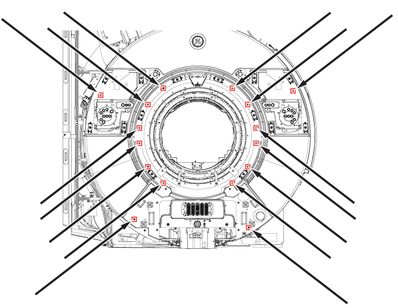
- Lift up the magnet front cover off of the front cover pins.
- Disconnect cable run M3379 from the GE logo and enclosure LEDs.
- Remove magnet front cover from magnet.
