
- SIGNA™ Hero 3.0T Service Methods
- 5852800-8EN Revision 1.0
- 00000018WIA302DEE20GYZ
- id_131060646.0
- Nov 9, 2020 11:39:03 AM
Laser Light Check and Alignment
Prerequisites
| Required persons | Preliminary requirements | Procedure | Finalization |
|---|---|---|---|
| 1 | Not Applicable | 15 minutes | Not Applicable |
| Item | Quantity | Effectivity | Part number | Manufacturer |
|---|---|---|---|---|
| Non-Ferrous Allen Wrench Set | 1 | - |
| - |
| Non-Ferrous Flat Blade Screwdriver | 1 | - |
| - |
About this task
This procedure describes Laser Light check and alignment. Axial laser light position is at 8mm away from Bridge end. And, cradle is used for adjustment jig.
Procedure
- Set the cradle as follows to use the cradle as alignment jig.
Figure 1. Cradle preparation 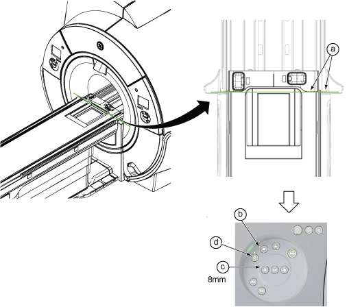
- Check for proper alignment.
-
The axial light should align with the “joint of cradle”.
-
The sagittal light should align with the middle line of the cradle.
If alignment is correct, you are done with this procedure. Otherwise, continue with the steps that follow.
Note: “Joints of cradle end cover and cradle on each side” are now located at 8mm away from Bridge end.Figure 2. Proper Alignment 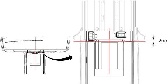
-
- For most of cover, Remove the two snap-in trim ring side sections.
Figure 3. Trim Ring Side Sections 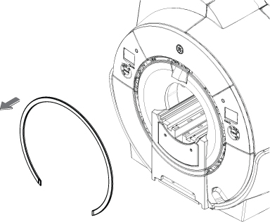
- For most of cover, Remove the laser light cover by removing two screws. Cover is held by two poppers and snaps off.
Figure 4. Remove Laser Cover 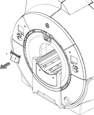
- Change the positioning of the alignment lights by moving the
joystick. Adjust the alignment via the joystick so that the axial
light (x-axis) is aligned to the bridge and endcap joints on both
sides of the bridge and the sagittal light (z-axis) is centered down
the middle of the bridge. See Figure 2 for proper
alignment.Note: There is only one joystick to adjust the laser light.
Figure 5. Adjusting Laser Lights With Single Joystick 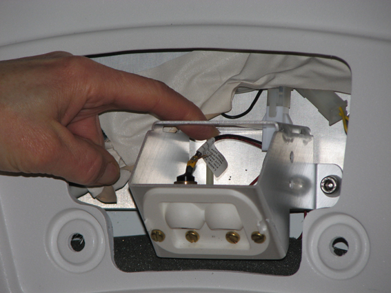
Finalization
- Perform DQA Calibration to calibrate isocenter following the instructions in DQA II Tool and Troubleshooting.
- If this is just an adjustment and no further calibrations are needed, then perform a SAVEINFO to save current system calibrations.