
- SIGNA™ Hero 3.0T Service Methods
- 5852800-8EN Revision 1.0
- 00000018WIA3095F010GYZ
- id_20032877.19
- Oct 26, 2021 8:21:53 AM
Connecting to and testing the PA port E connector
Connecting to and testing the PA port E connector.
Procedure
- Disconnect the PE coil ports from the patient table. To avoid equipment damage the cables should be removed from the PA coil in the following order: C3-C2-C1.
Result
Three PE coil ports are part of the PA port E connector:- PE coil port C3 (white connector)
- PE coil port C2 (black connector)
- PE coil port C1 (black connector)
Figure 1. Patient table with cradle hardtop cover removed, showing PA port E connector (cable bundle) and PE coil ports (cables with connectors) 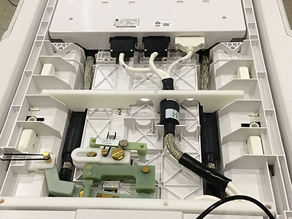
- Connect the PE coil ports in the order given to avoid equipment damage.
- Attach C8 (37-pin to 25-pin sub-D male-female) to 37pin connector at TDI PA and to J2 of the MCRv tool.
- Attach 16 pin connector at TDI PA C1 to J3 of the MCRv tool.
- Attach 16 pin connector at TDI PA C2 to J4 of the MCRv tool.
Figure 2. PA port E connected to MCRv tool 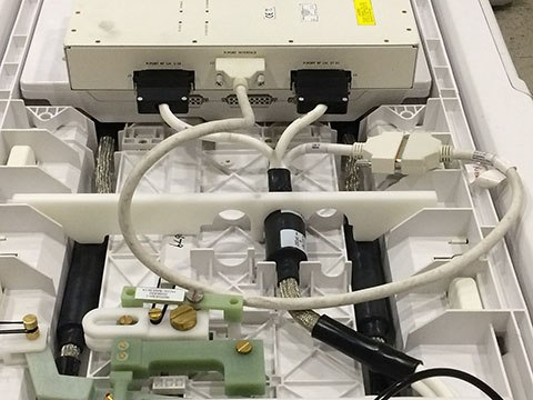
Results
Note: If a test fails for PA Port E:
- Make sure that the connectors are firmly seated.
- Make sure that the screws are properly tightened.
- Rerun the test.
If the test fails again:
- Reseat the connectors.
- Reseat all test cable connections to the MCRv tool connectors.
- Rerun the test.
If the test continues to fail, run the test at the corresponding DPP RRx port.
| Correspondence between DPP RRx module and PA port E connection | |
|---|---|
| DPP RRx module | Other coil connection |
| DPP RRX 3 | PA Port E |
Finalization
- Disconnect cable connectors C3, C2, and C1 from the MCRv tool.
- Connect cable connectors C1, and C2, and C3 to the posterior array coil.
Figure 3. Connectors 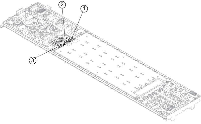
1 C1 2 C2 3 C3