
- SIGNA™ Hero 3.0T Service Methods
- 5852800-8EN Revision 1.0
- 00000018WIA30208110GYZ
- id_20040806.12
- Oct 11, 2021 6:31:29 PM
Checking the ECG leads
Testing the electrical connections on the ECG cables
Prerequisites
| Personnel requirements | |||
|---|---|---|---|
| Required persons | Preliminary requirements | Procedure | Finalization |
| 1 | - | 5 minutes | - |
| Tools and Test Equipment | |||
|---|---|---|---|
| Description | Quantity | Part Number | Manufacture |
| Ohmmeter | 1 | - | - |
Procedure
- If not already done, disconnect the ECG cables from the PAC and from each other.
Figure 1. PIN Diagram of ECG Lead 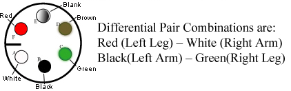
- Check the impedance of the ECG cables from each lead at point to its respective connection at point C. The impedance should be 0 ohms.
Figure 2. Connections A and B on ECG Cables 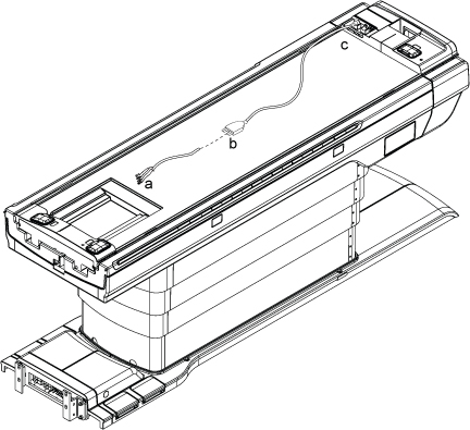
- Connect the white high impedance MRI ECG lead wires to the grey ECG patient cable by matching the colors on the white cable to the colored dots on the grey cable.
Figure 3. PIN diagram of ECG lead 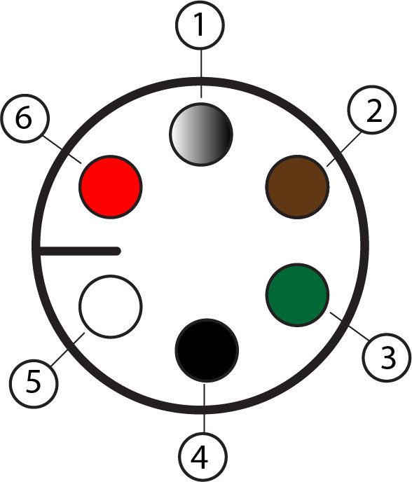
Table 1. PIN diagram of ECG lead Callout Color 1 Blank 2 Brown 3 Green 4 Black 5 White 6 Red Differential pair combinations are
- Red (left leg) - White (right arm)
- Black (left arm) - Green (right leg)