Adjusts the hydraulic cylinder to set the tabletop height.
Prerequisites
| Personnel requirements |
|---|
| Required persons | Preliminary requirements | Procedure | Finalization |
|---|
| 1 | - | 10 minutes | - |
| Tools and test equipment |
|---|
| Item | Quantity | Part number | Manufacturer |
|---|
| 150 mm Plastic Dial Caliper with Metric Readout | 1 | 5916010 | - |
| Nonmagnetic Titanium Service Tool Kit, Small Set | 1 | 5113258 | - |
Procedure
- Measure the distance from the horizontal bearing surface to the laser line at the labeled locations.
Note: Measure approximately 60 mm from the edge of the bridge to avoid the profile change.
Figure 1. Height measurement points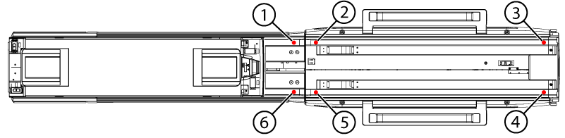
| 1 | Measurement point G |
| 2 | Measurement point D |
| 3 | Measurement point C |
| 4 | Measurement point A |
| 5 | Measurement point B |
| 6 | Measurement point E |
Figure 2. Vertical measurement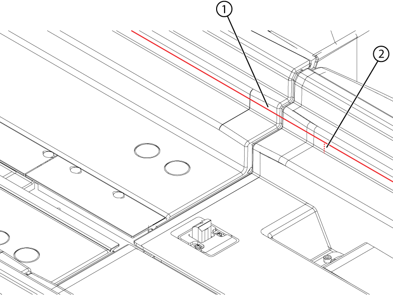
| 1 | Laser |
| 2 | Vertical measurement |
- Enter the measurements in the Table Height - Run 2 table on the Table Leveling&Height sheet of the Alignment Data Sheet Macro.
- Turn the nut at the top of the hydraulic cylinder as indicated by the Table Height Calculator table.
Note: To make the nut rotatable by hand:
- Raise the table to its highest point.
- Lower the safety rod.
- Press the down pedal while pushing the cylinder rod down.
Note: Rotate the nut counter-clockwise to raise the tabletop and clockwise to lower it.
Figure 3. Height adjustment nut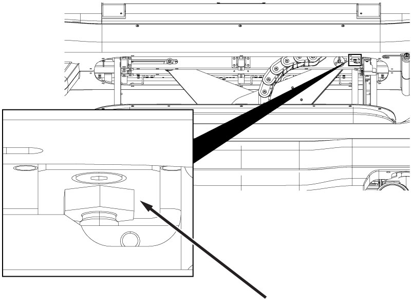
- Repeat Step 1 through Step 3 until the Difference cells in the Table Height - Run 2 table are green.
- Raise the safety rod when work under the table is complete.
- Measure the height difference between the table top and the bridge top on both the left and right sides.
Figure 4. Table height measurement point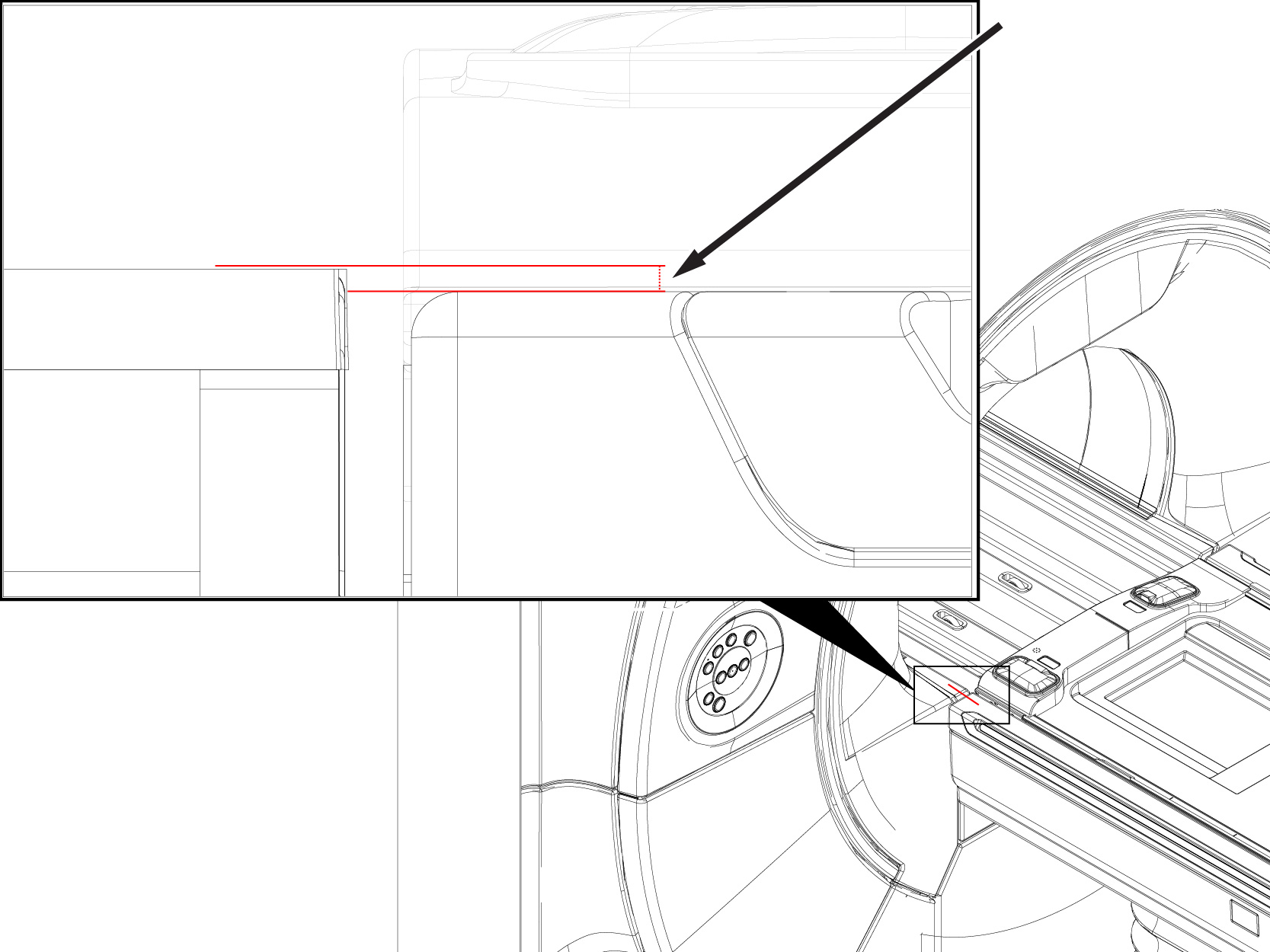
- Record the measurement for ICW.
