
- SIGNA™ Hero 3.0T Service Methods
- 5852800-8EN Revision 1.0
- 00000018WIA30596E40GYZ
- id_20202073.7
- Apr 23, 2020 8:52:27 PM
Adjusting the flipper assembly
Adjusts the flipper assembly height and table position.
Prerequisites
| Personnel requirements | |||
|---|---|---|---|
| Required persons | Preliminary requirements | Procedure | Finalization |
| 1 | - | 10 minutes | - |
| Tools and test equipment | |||
|---|---|---|---|
| Item | Quantity | Part number | Manufacturer |
| Stainless Steel Ruler | 1 | 46-198452P2 | - |
| Nonmagnetic Titanium Service Tool Kit, Small Set | 1 | 5113258 | - |
Procedure
- Measure the distance from the top surface of the stop block to the top surface of the flipper housing.
Figure 1. Stop block measurement 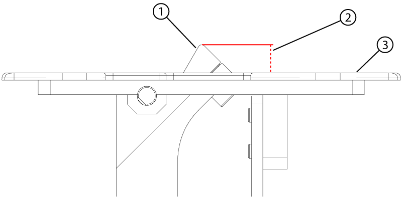
1 Stop block 2 Stop block height above housing 3 Flipper housing - If the measurement is not within specification, do the following to adjust the flipper height:
Flipper housing revision Height specification Rev 3 (white painted) 12 ± 0.5 mm Rev 4 (unpainted aluminum) 13 ± 0.5 mm - Remove the screw holding the cable to the flipper housing.
Figure 2. Flipper housing cable 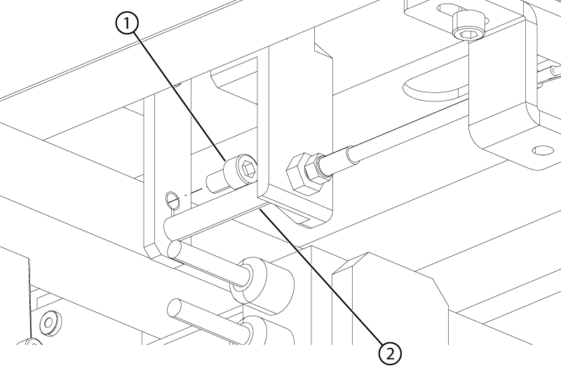
1 Flipper housing cable screw 2 Flipper housing cable spacer - Remove the four screws and four washers securing the flipper assembly to the tabletop.
Figure 3. Flipper tabletop hardware 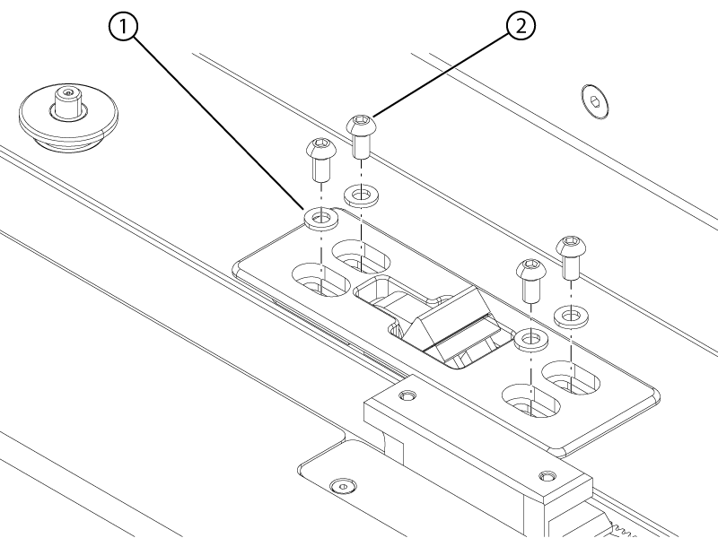
1 Washer 2 Screw - Adjust the quantity of 0.25 mm shims until the distance is within specifications.
Figure 4. Stop block shims 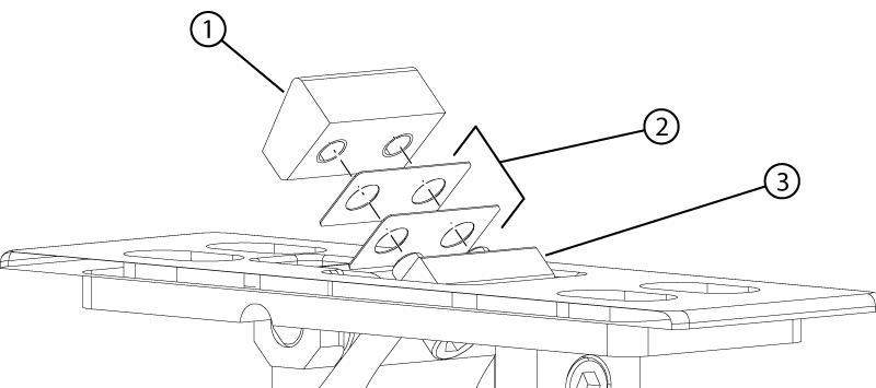
1 Stop block 2 Shim 3 Flipper housing
- Remove the screw holding the cable to the flipper housing.
- Adjust the flipper housing such that the distance from the front surface of the cradle stopper to the front surface of the flipper housing is 293 (+1/-0) mm.
Figure 5. Flipper position 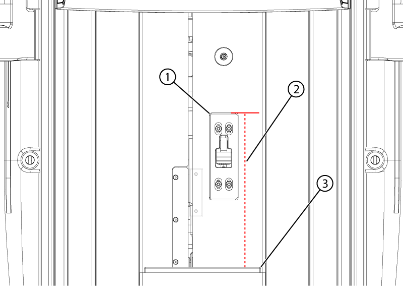
1 Flipper housing 2 293 (+1/-0) mm 3 Cradle stopper